Matching Model and Pick Point Editor
This section introduces the user interface of Matching Model and Pick Point Editor.
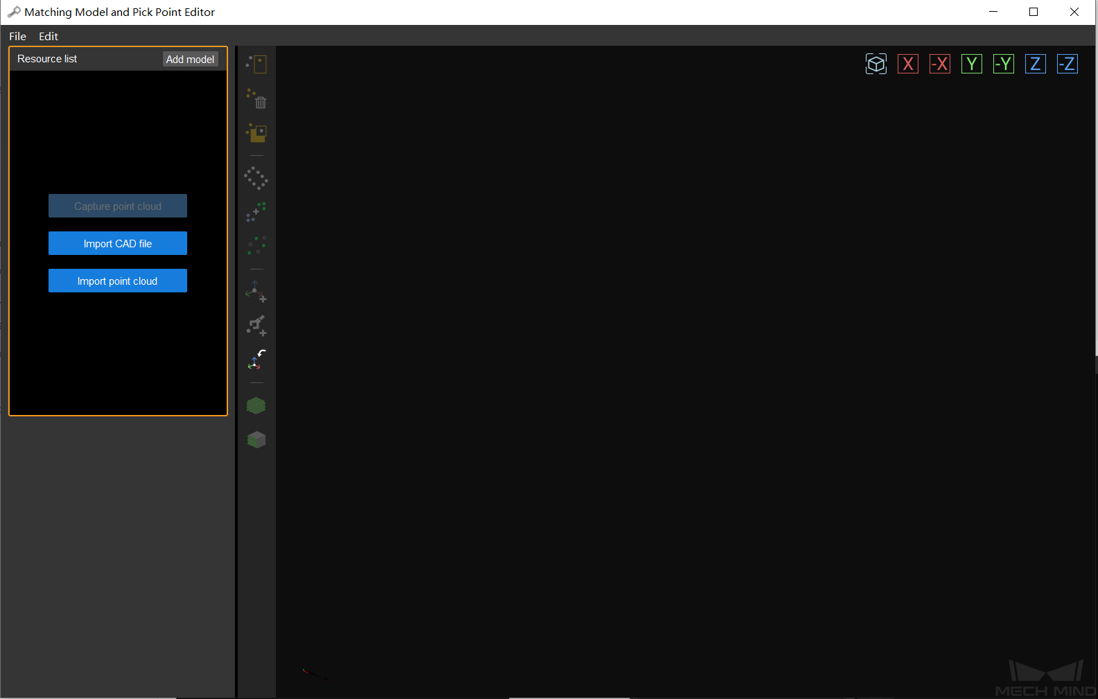
When no resource file is imported, the start screen of Matching Model and Pick Point Editor is shown as below. You can click the buttons in the upper left corner to import the resource files.
Hint
When there is a Capture Images from Camera in the project, the Capture point cloud button will be activated.
After a resource file is imported, the user interface of Matching Model and Pick Point Editor, as shown below, can be divided into five parts:
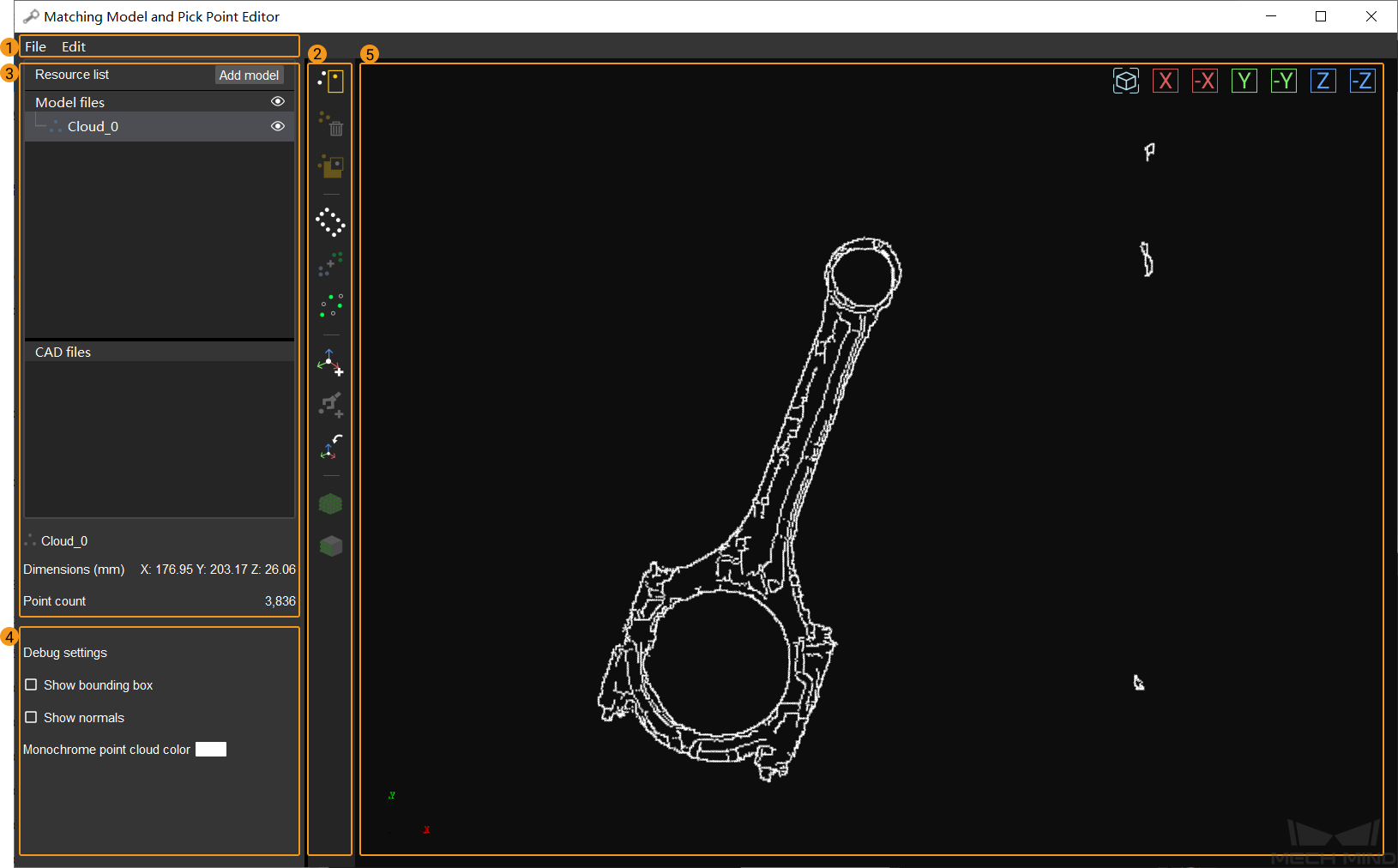
Toolbar
The toolbar includes buttons used in point cloud model generation, point cloud model editing, and pick point addition.
Button |
Description |
|
Select points in the point cloud |
|
Remove selected points from the point cloud |
|
Invert the point selection in the current point cloud |
|
Estimate the edge of the point cloud with the 3D method |
|
Merge point clouds |
|
Downsample a point cloud |
|
Add a pick point by adding a pose |
|
Add a pick point by teaching |
|
Import an existing pick point file |
|
Generate a point cloud of the CAD model’s surface |
|
Generate a point cloud of only the part visible in the current view of the CAD model’s surface |
Resource List
The resource list includes the Model files list and CAD files list.
Model files
All point cloud model files, pick point files, and geometric center files saved under Project Folder/resource/model_editor/matching_source are listed here.
Mouse action |
Function |
Click |
Hide this file in the visualizing space. Clicking again makes the file visible. |
Double-click a file name |
Rename the file |
Drag |
|
Right-click a point cloud model |
Can copy or delete this model |
Right-click a pick point/geometric center |
Can copy, delete, or set this point as geometric center and/or pick point |
Hint
If a point cloud model only has one pick point, then the Set as geo. center option in the right-click menu of this pick point cannot be unselected.
CAD files
All CAD model files saved under
Project Folder/resource/model_editor/cad_filesare listed here.Similar to the Model files list, clicking the
 next to a file name hides the file in the visualizing space. Clicking again makes the file visible.
Right-clicking a file name gives the option to remove the file from the list, but this will not delete the CAD file saved in the above directory.
Parameters and Display Pane
The parameters and display pane is the region below the CAD files list. When you select a point cloud model, a pick point/geometric center, or a CAD file, this pane will display the functions corresponding to the type of file.
When a point cloud model is selected, you can choose whether to Show bounding box and Show normals, and change the Monochrome point cloud color in this pane.
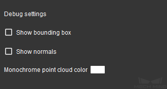
Select Show bounding box to show the bounding box of the selected point cloud model.
Select Show normals to show normals of the selected point cloud model.
Double-click the white rectangle next to Monochrome point cloud color to change the display color of the point cloud model.
Hint
The display color of an imported color point cloud cannot be changed.
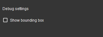
When a CAD file is selected, this pane displays the dimensions of the CAD model’s bounding box, and the Show bounding box option.
Select Show bounding box to show the bounding box of the selected CAD model.
When a pick point/geometric center is selected, this pane displays the Pose Editing Widget. For detailed description, please refer to Pose Editing Widget.
Visualizing Space
The visualizing space is used for the visualization of point cloud models and CAD files opened in Matching Model and Pick Point Editor and view adjustment.
You can adjust your view through the following mouse actions.
Mouse action |
Function |
Left-button drag |
Rotate the view |
Right-button drag or scroll |
Zoom |
Drag with the scroll wheel |
Pan the view |
You can also use the buttons in the upper right of the visualizing space to achieve the following view adjustments.
Button |
Description |
|
Zoom to fit, and center the selected file in the visualizing space |
|
View along the positive X-axis |
|
View along the negative X-axis |
|
View along the positive Y-axis |
|
View along the negative Y-axis |
|
View along the positive Z-axis |
|
View along the negative Z-axis |