Details of the Project
Application Scenario of High Precision Positioning
In automotive assembly, many processes require high position accuracy, including wheel hub locating, tire tightening, and gearbox assembly, etc.
Traditional automated production processes cannot provide robots with accurate location information of objects and require human intervention, thus having a low efficiency.
To solve this problem, Mech-Mind Robotics proposed a 3D vision positioning technology in which the visual recognition results and model files are matched multiple times to accurately obtain the 3D pose information of objects, thus improving the efficiency of high precision assembly processes.
Mech-Vision Project Workflow
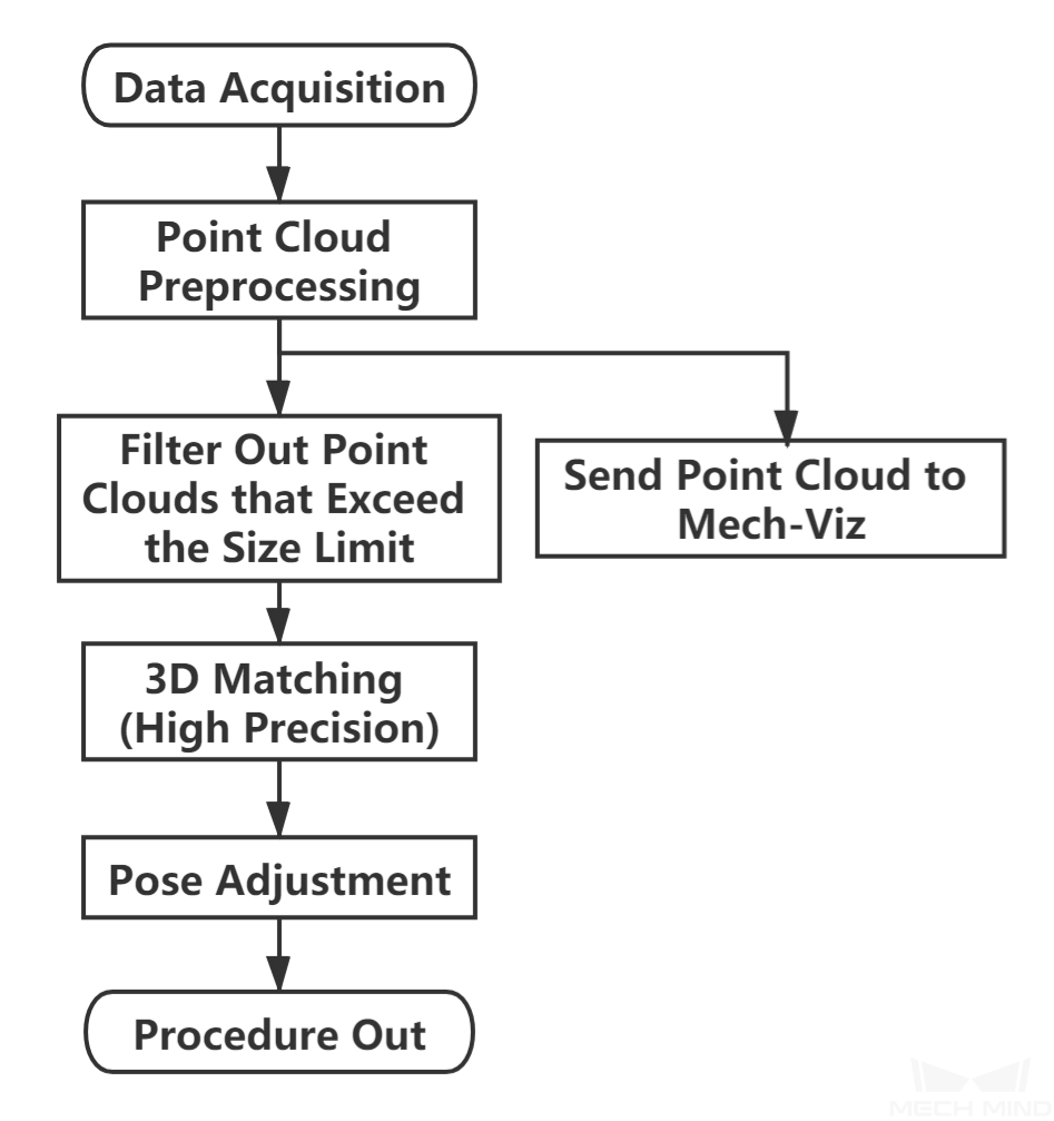
The workflow of a Typical Project for High Precision Positioning is shown in Figure 1.

Figure 1. The workflow of High Precision Positioning
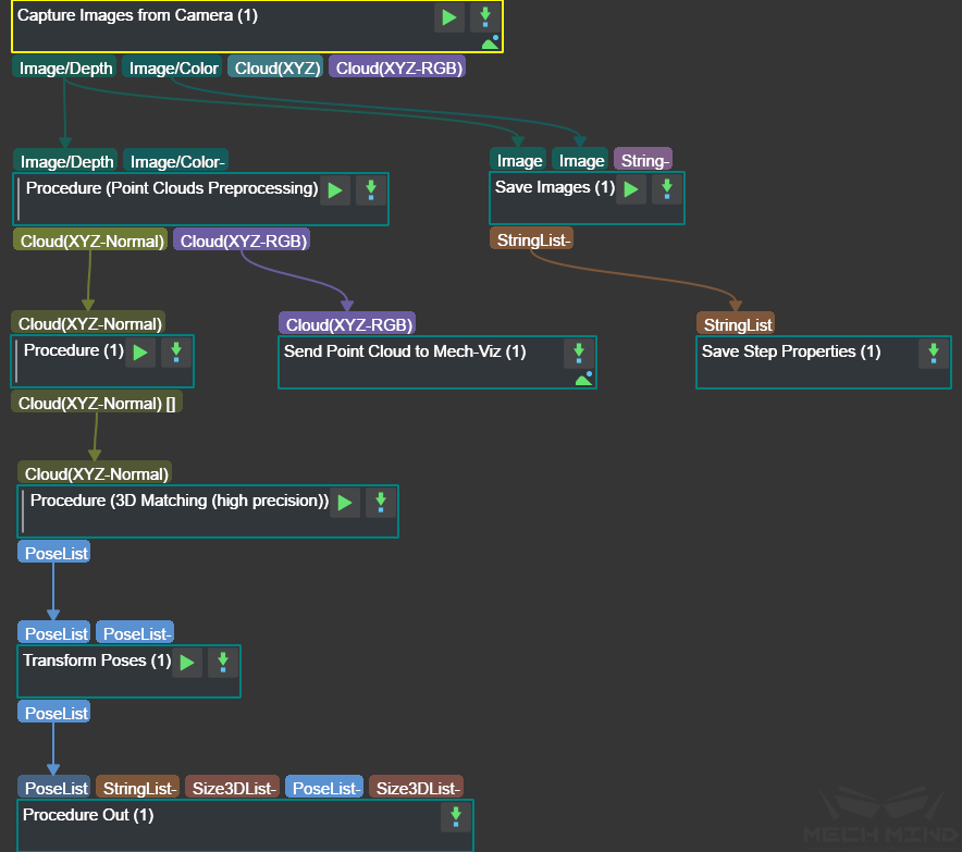
The graphical programming of this project is shown in Figure 2.

Figure 2. The graphical programming of a Typical Project for High Precision Positioning
Steps and Procedures
A Procedure is a functional program block that consists of more than one Step.
Capture Images from Camera
This Step obtains the color images and depth maps of the scene from the camera and provides data for the subsequent visual calculation.
Please see Capture Images from Camera for details about this Step.
Point Cloud Preprocessing
This Procedure facilitates and shortens the processing time for the subsequent calculations. Point Cloud Preprocessing generates a raw point cloud from the depth map and the color image, deletes the outliers, calculates the normals for the point cloud, and in the end extracts the part of the point cloud within the ROI.
For details about this Procedure, please see Point Cloud Preprocessing.
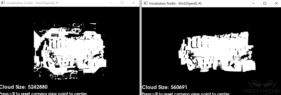
A sample result of Point Cloud Preprocessing is shown in Figure 3. The original point cloud is on the left and the preprocessed point cloud is on the right.

Figure 3. A sample point cloud before and after Point Cloud Preprocessing
Filter Out Point Clouds That Exceed the Limit
This Procedure filters out point clouds that affect 3D matching to improve the accuracy of matching.
Please see Filter Out Point Clouds That Exceed The Limit for details about this Procedure.
3D Matching (High Precision)
In this Procedure, 3D Coarse Matching is followed by two rounds of 3D Fine Matching to obtain a list of finely calculated poses.
Please see 3D Matching (High Precision) for details about this Procedure.
The figures below show sample matching results.
The left figures are the front views and the right figures are the side views. In the point clouds, the red point clouds are the models that are matched with the object point clouds in white.
The coarse matching result is shown in Figure 4. If the model and point cloud do not well overlap, the matching has a relatively large error. The final result after two rounds of fine matching is shown in Figure 5.

Figure 4. A sample result of 3D Coarse Matching

Figure 5. A sample result of 3D Matching (High Precision)
Adjust Poses
This Step is for adjusting the poses.
Please see Pose Editor for instructions on adjusting poses.