Capture Images from Camera
Function
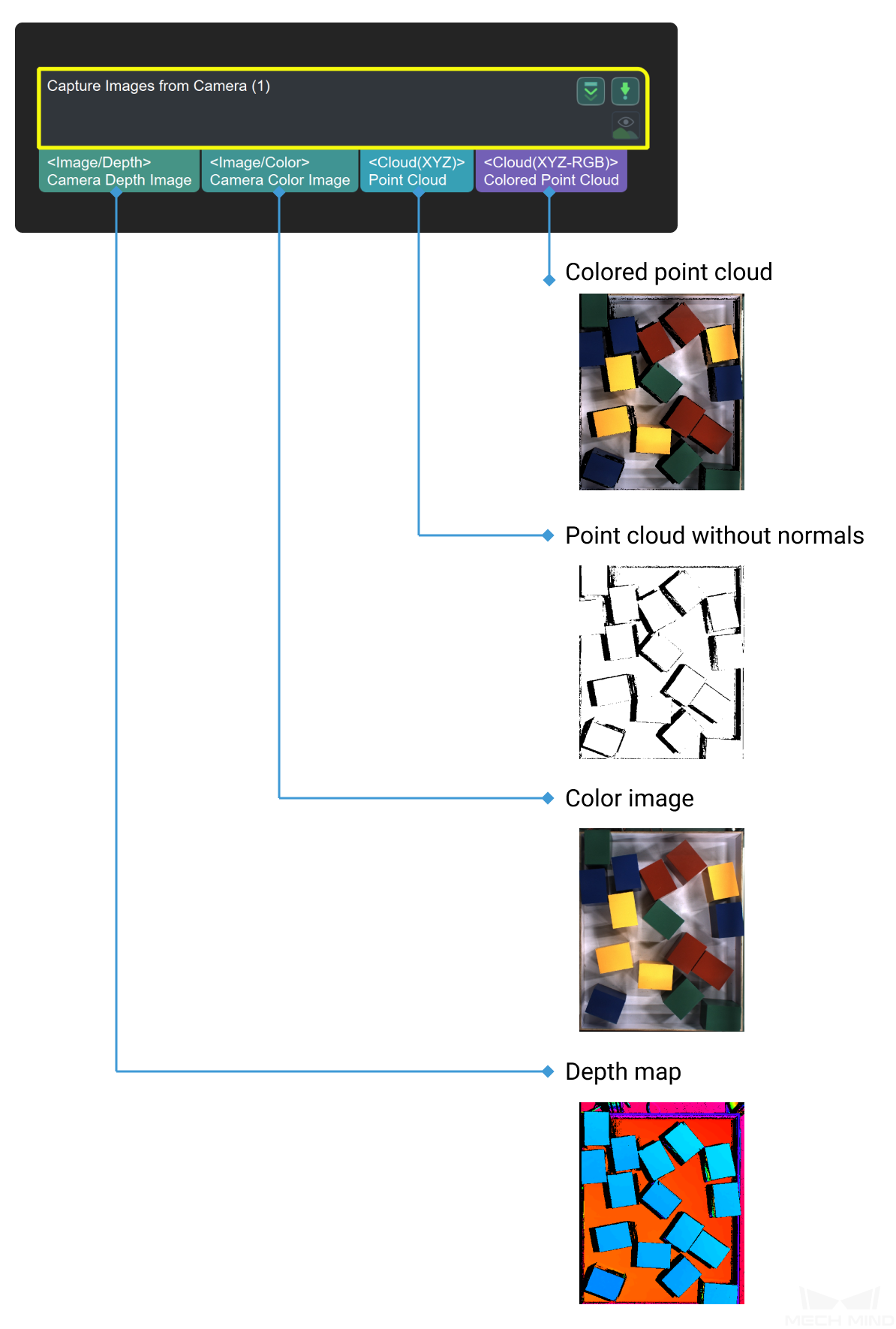
This Step is used to obtain color images, depth maps, and point clouds from a real or virtual camera.
Sample Scenario
Used as the initial input entry of a vision project, this Step collects data from a Mech-Eye Industrial 3D Camera or third-party camera or acts as a virtual camera for inputting simulated data source.
Input and Output
Parameter Tuning
Use a Real Camera
Camera Settings
- Camera Type
- Default setting: Mech-EyeOptions: External2D, LMI, Mech-EyeTOF, Mech-EyeInstruction: Select the camera type according to the real camera connected.
- Camera ID
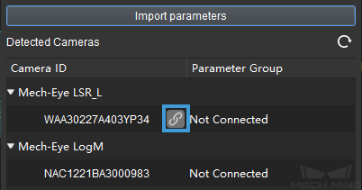
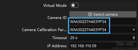
- Default setting: CAM00000Instruction: Click Select Camera, and select the camera you want to connect and corresponding parameter group, and then the camera ID will be automatically filled.
Select the camera you want to connect in the pop-up window, and click
 .
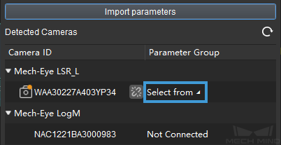
.Once the camera is connected successfully, the
 icon will turn into
  , and then you can click Select from and select the camera parameter group in the drop-down list.
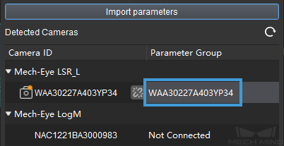
If the parameter group is selected successfully, it will be displayed as shown below.
After the camera is connected and the parameter group is selected successfully, the Camera ID and Camera Calibration Parameters will be automatically filled, as shown below.
- Camera Calibration Parameters
- Instruction: The camera calibration parameters will be automatically filled with the camera ID.
- Timeout
- Default setting: 20sDescription: The response timeout period of the camera. If the camera fails to capture any picture within the set time, it is a timeout. Then the camera will attempt to capture images again. An error will be reported if there are three consecutive timeouts.
- IP Address
- Default setting: 127.0.0.1Description: The IP address of the camera. After the camera is connected and the parameter group is selected successfully, the camera IP address will be automatically filled.
- Camera Model
- Default setting: UnknownDescription: The model name of the connected camera will be filled automatically. This parameter cannot be adjusted manually.
- 2D Image Type
- Default setting: Internal IR ImageOptions: Internal IR Image, External Color ImageDescription: You can select the 2D Image Type according to the requirement when a DEEP or LSR series camera is used. The Internal IR Image is the same as the one output by a Laser series camera, which is a monochrome 2D image. Internal IR images do not need to be rectified as their reference frame is the same as that of the depth map. External color images are captured by the 2D color camera, and they need to be rectified before being used.
- Rectify to Depth Map
- Default setting: UnselectedDescription: This option is only available when External Color Image is set as the 2D Image Type. It is used to rectify the reference frame of the color image to the reference frame of the depth map.
- Recapture Times
- Default setting: 3Recommended value: 3Description: The upper limit of image capturing times in one execution of the Step. The failed attempt(s) to capture the image will be included in the Recapture Times.
- Robot Service Name in Mech-Center
- Default setting: NullDescription: Enter the robot service name, which should be the same as the name of the robot connected in Mech-Center.
Use a Virtual Camera
Camera Settings
- Virtual Mode
- Default setting: UnselectedInstruction: Select this option when a virtual camera is used.
- Camera Calibration Parameters
- Instruction: Once the Data Path is selected, Camera Calibration Parameters will be automatically filled. If there are multiple sets of camera calibration parameters, please select the one you need in the drop-down list.
- Data Path
Hint
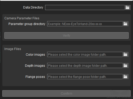
If any one of the following descriptions is true when you select the data path, a Virtual Camera Assistant will be triggered to help you select the image data.
There is no data in the selected folder.
There are multiple sets of data in the selected folder.
There is no color image, depth map, or intrinsic and extrinsic parameters in the selected folder.
When you select the image data path for projects in Eye In Hand mode, the image data should be arranged as shown in the figure below.

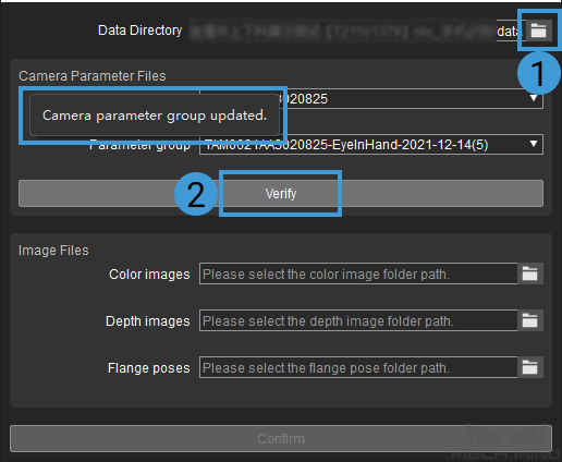
In the pop-up Virtual Camera Assistant window, click
 to select the data directory, and then the Camera ID and Parameter group will be automatically filled in the window. Then click Verify, and a “Camera parameter group updated” message will appear.
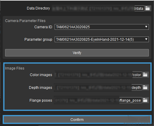
Afterwards, click
 to select the image data, i.e., color image, depths maps, and flange poses. Click on Confirm after selecting the data.
Lastly, click OK in the pop-up Setup Complete window.
When you select image data path for projects in Eye To Hand mode, the image data should be arranged as shown in the figure below.
- Play Back Mode
- Default setting: SequentialOptions: Sequential, Repeat One, Repeat All, RandomDescription: Select the mode according to image reading order you need.
- Current Frame Name
- Description: Display the serial number and timestamp of the currently read image.
Attention
The virtual mode of this Step does not support reading image data dynamically. Therefore, please re-select the data path if there is any modification of the image in the selected data path, or else there may be missing images in the drop-down list of the current frame name.
