Turnover Box
This section provides guidance on using the Turnover Box Depalletizing project. The overview of the project is as follows.
Workpiece |
Rectangular turnover box without lids, orderly stacked in multiple overlapping layers, no obvious reflection, and point cloud missing less than 20% |
Carriers |
Tray |
Working distance |
1200–3500 mm |
Technical specifications |
Recognition and positioning accuracy: ± 4 mm |
Recognition success rate: more than 99.9% |
|
Vision cycle time: within 4 s |
Project Description
The following section introduces the Turnover Box project in terms of applicable scenarios and technical specifications.
Applicable Scenarios
This section introduces the applicable scenarios of this project in terms of the workpiece and carrier.
Workpiece
This project is applicable to turnover boxes with the following characteristics.
Workpiece Characteristic |
Application Case |
Example |
Type of workpiece |
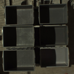
Applicable to turnover boxes without lids; also applicable to turnover boxes that are fit tightly together |
|
Not applicable to turnover boxes with lids |
|
|
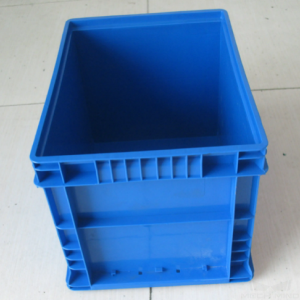
Shape and size |
Rectangular |
|
Material |
Plastic |
|
Reflectivity |
No obvious reflection |
|
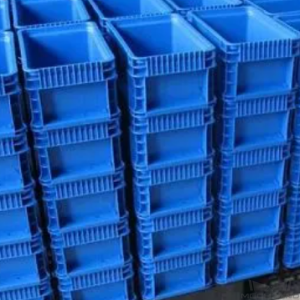
Stacking |
Multiple layers orderly stacked |
|
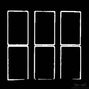
Point cloud quality |
A small amount of the turnover box edge’s point cloud missing is allowed (Missing point cloud not exceeding 20%) |
|
Not applicable to cases where too much of the point cloud is missing and where the edges of the turnover boxes are blocked by other objects |
|


Carriers
This project is applicable to carriers with the following characteristics.
Carrier Characteristic |
Application Case |
Example |
Type of carrier |
Tray 1 |
|
Tray 2 |
|

Technical Specifications
The technical specifications of the Turnover Boxes Depalletizing project are as follows.
Recognition and positioning accuracy: ±4 mm
Recognition success rate: more than 99.9%
Vision cycle time: within 4 s
Note
Vision cycle time refers to the amount of time for the project to execute once, from image capturing to outputting vision result.
Project Planning
Layout
Workstation Layout
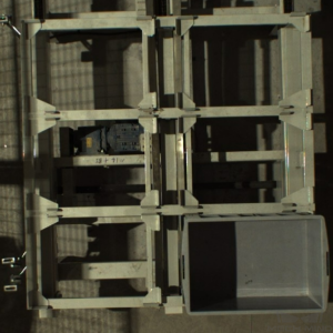
The layout of the workstation is shown below.

The workflow in the workstation is as follows:
The turnover boxes are moved to the depalletizing area by the AGV.
The robot sends an image-capturing command to the vision system, and the camera will be triggered to capture the image for recognition. Then the vision system sends the position information of the turnover box to the robot.
Guided by the position information sent by the vision system, the robot picks the turnover box and places it on the conveyor belt.
Repeat the above steps until the depalletizing is completed.
Hardware of the Vision System
Recommended Specification |
Description |
|
Camera |
DEEP |
Recommended mounting method: eye-to-hand; working distance: 1200-3500 mm |
IPC |
Standard model without a GPU |
Processor: CPU I5-12400 |
RAM: 16G DDR4 |
||
HDD: 256G SSD |
||
Power supply: DC24V 7.5A |
||
Operating system: Windows 10 21H1 (genuine) |
||
WIFI module |
Robot Tool
The 2 types of robot tools usually used in the Turnover Box project are the clamp gripper and the right-angle clamp gripper. When the turover boxes fit closely to each other, the right-angle clamp gripper is recommended to use.
Clamp Gripper
The clamp gripper is shown in the figure below.
Gripper Description:
This gripper picks the turnover box with the two parallel jaws.
Gripper Advantages:
Applicable to turnover boxes of various dimensions.
The surface of the gripper which directly contacts the box is made of soft material, which has a certain buffering effect and can reduce the degree of deformation of the box.
Gripper Disadvantages:
This type of gripper cannot be used to depalletize boxes that fit closely to each other.
Right-Angle Clamp Gripper
The right-angle clamp gripper is shown in the figure below.

Gripper Description:
This gripper clamps two adjacent sides of the turnover box to pick and then put down the two lifting hooks to fix the box. When placing, the two lifting hooks will be taken off and the clamps will be opened to place the turnover box.
Gripper Advantages:
This type of gripper can be used to depalletize boxes that fit closely to each other.
Applicable to turnover boxes of various dimensions.
The surface of the gripper which directly contacts the box is made of soft material, which has a certain buffering effect and can reduce the degree of deformation of the box.
Gripper Disadvantages:
This type of gripper is not applicable to pick turnover box with a too heavy weight (e.g. 50 kg).
Vision Solutions
Communication Method
It is recommended to use the Standard Interface for communication.
I. Switch Mech-Vision Recipe |
|||
Robot -> IPC |
Request Command |
Mech-Vision Project ID |
Recipe Number |
103 |
The number on the left of the project name in Mech-Vision’s project list |
1-99 |
|
Example |
103, 1, 2 |
||
IPC -> Robot |
Returned Command |
Status Code |
|
103 |
1107: The recipe is switched successfully 1012: The Mech-Vision recipe number does not exist |
||
Example |
103, 1107 |
||
II. Start Mech-Viz Project |
|||
Robot -> IPC |
Request Command |
Pose Type |
Robot Pose |
201 |
0: No robot pose sent to Mech-Viz 1: Send current joint positions and flange pose of the robot to Mech-Viz 2: Send joint positions of a specific start point to Mech-Viz |
The pose data of the robot in the form of the specified “pose type” |
|
Example |
201, 1, 0, -20.632, -107.812, 0, -92.818, 0.003 |
||
IPC -> Robot |
Returned Command |
Status Code |
|
201 |
2103: The execution is successful 2008: An error occurs when the project is running …… |
||
Example |
201, 2103 |
||
III. Select Mech-Viz Branch |
|||
Robot -> IPC |
Request Command |
ID of the Branch Step |
Number of the Exit Port |
203 |
This parameter should be a positive integer. It is used to specify the ID of the branch Step along which the project will proceed. |
This parameter should be a positive integer. It is used to select the exit port of the Step that the project will take. |
|
Example |
203, 1, 1 |
||
IPC -> Robot |
Returned Command |
Status Code |
|
203 |
2105: The execution is successful 2018: The number of the exit port is invalid …… |
||
Example |
203, 2105 |
||
IV. Get Planned Path (Recommended) |
||||||
Robot -> IPC |
Request Command |
Type of Waypoint |
||||
205 |
1: Joint positions 2: TCP |
|||||
Example |
205, 1 |
|||||
IPC -> Robot |
Returned Command |
Status Code |
Whether All Waypoints Have Been Sent |
Number of Waypoints |
Position of “Vision Move” |
Waypoint |
205 |
2100: The execution is successful 2007: Failed to plan a path …… |
0: NOT all waypoints have been sent 1: All waypoints have been sent |
Default range: 0-20 If there are more than 20 waypoints in the path, execute this command multiple times. |
The position of the first Vision Move waypoint in the path |
Object pose Label Speed |
|
Example |
205, 2100, 1, 2, 2, 8.307, 15.163, -142.177, -2.775, -31.440, -96.949, 0, 64 |
|||||
V. Get Vision Targets (For applications that use Mech-Vision but not Mech-Viz; not recommended) |
||||||
Robot -> IPC |
Request Command |
Mech-Vision Project ID |
||||
102 |
The number on the left of the project name in Mech-Vision’s project list |
|||||
Example |
102, 1 |
|||||
IPC -> Robot |
Returned Command |
Status Code |
Whether All Vision Targets Have Been Sent |
Number of TCP |
Reserved Fields |
Vision Target |
102 |
1100: The execution is successful 1102: No vision points …… |
0: NOT all vision points have been sent 1: All vision points have been sent |
Default range: 0-20 |
This field is not used. The default value is 0. |
Object pose Label Speed |
|
Example |
102, 1100, 1, 1, 0, 95.780, 644.567, 401.101, 91.120, -171.130, 180.0, 0, 0 |
|||||
For details, refer to the Standard Interface Communication section.
Project Description
The general workflow of this project is shown in the diagram below.
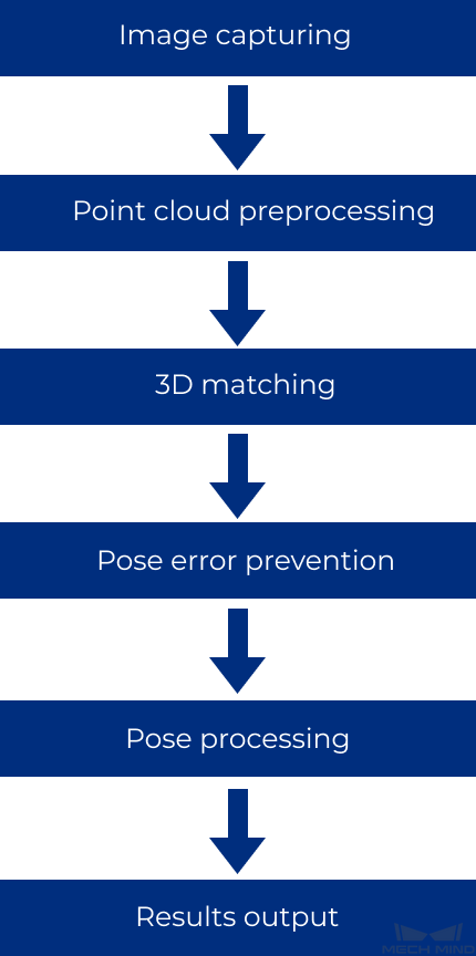
Image capturing: Obtain the color image and depth map of the plastics turnover box.
Point cloud preprocessing: Preprocess the original point cloud of the turnover box and extract the point cloud of the turnover box’s top edge to shorten the processing time of the subsequent Steps.
3D matching: Use the edge point cloud model to perform matching with the point cloud of the turnover box’s top edge obtained from point cloud preprocessing, in order to obtain candidate picking poses.
Pose error prevention: Filter out unqualified picking poses according to set rules and determine whether any false positive and false negative occurred during recognition.
Pose processing: Transform and sort the picking poses.
Result output: Send the results of the current project to the backend service.
Generate Point Cloud Model and Add Pick Point
Generate point cloud model:
Method: Use the Estimate Point Cloud Edges by 2D Method Step is used to extract the edge point cloud model. Set the 2D Line Width parameter in this Step to 2 pixels.
Reason: When the point cloud quality is high, the 2D edge model can achieve higher pose matching accuracy than the 3D edge model. Meanwhile, you can set the model line width for 2D edge models, which makes 2D edge models more stable during the matching process compared to 3D edge models.
Add pick point:
Setting method: Directly add and adjust a pick point in Matching Model and Pick Point Editor .
Reason: The turnover box are usually rectangular in shape. It is easy to adjust the pick point by drag-and-drop, and the accuracy of such adjustment meets the requirements on site.
Project Difficulties
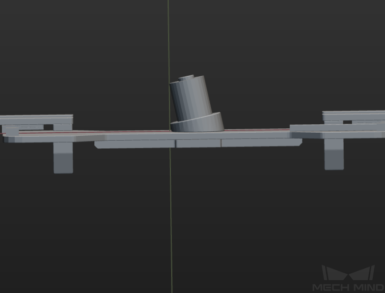
When the turnover boxes fit tightly together, it is difficult to separate the point clouds of different turnover box with Point Cloud Preprocessing.
The point clouds of some turnover boxes are of poor quality, have missing parts, or have large surface fluctuations.
Some projects require a high recognition and positioning accuracy (For example, when the Z-axis of the pick point is perpendicular to the surface of the turnover box and points upward, the deviation of the picking pose Z-axis from the pick point Z-axis must be less than 0.5°).
Project Advantages
Edge matching used in this project increases the recognition accuracy.
This project has effective error-proofing Steps to prevent misrecognition, which ensures the stability of the project.
The gripper used in this project is applicable to depalletize boxes that fit closely to each other.
Project Deployment
Cautions
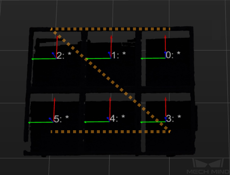
In this project, clamp gripper is usually used. For scenarios where the turnover box fit tightly together (as shown in the figure below), the gripper must be designed so that it does not collide with adjacent turnover boxes during picking.

Suggestions for Parameter Adjustment
Point Cloud Preprocessing
Point Cloud Clustering : To remove outliers and noise while preserving the point cloud of the turnover box edge, you need to adjust the parameters of the Point Filter and Point Cloud Clustering Steps. If there are objects inside the turnover box, use Point Cloud Clustering to separate the point cloud of the turnover box edge from that of the objects, otherwise the extraction of the edge point cloud will be affected.
Get Highest-Layer Points: Obtain the point cloud of the turnover box’s upper edge only.
Estimate Point Cloud Edges by 2D Method : Get a complete point cloud of the inner side of the turnover box’s top edge.
3D Matching
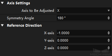
Point Axes of Poses to Given Direction : In order to reduce unnecessary rotation of the robot tool, set the Rectification Method to ROTATION, the Axis to Be Adjusted to X, the Symmetry Angle to 180°, and the X-axis Reference Direction to -1.0000.
Positional Error Prevention
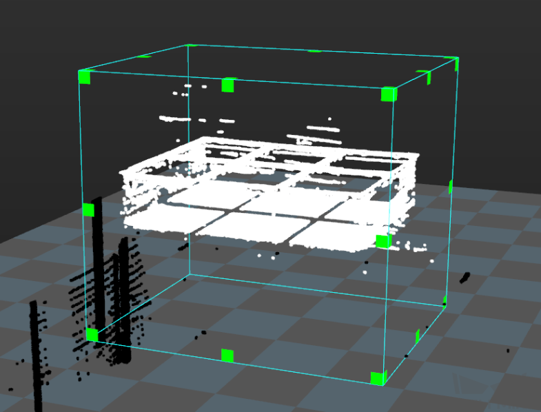
Collect Poses in 3D ROI: Set a 3D ROI to filter out poses outside the 3D ROI.
Validate Poses by Included Angles to Reference Direction: Change the Reference Direction parameters of this Step.

Check whether any false positive and false negative occurred: compare the projections of the extracted edge point clouds of the turnover boxes in the top layer to the projection of the edge point cloud of a single turnover box.
If Point Cloud Preprocessing is unable to only extract the point cloud of the turnover box’s top edge (as the input point cloud also contains the point cloud of the objects inside the turnover box), this error prevention procedure needs to be deleted, and other effective error-prevetion strategies can be taken.
Pose Processing
Sort 3D Poses: To be adjusted based on the on-site situations. SORT_BY_Z is selected by default.
Common Problems and Solutions
Problem 1
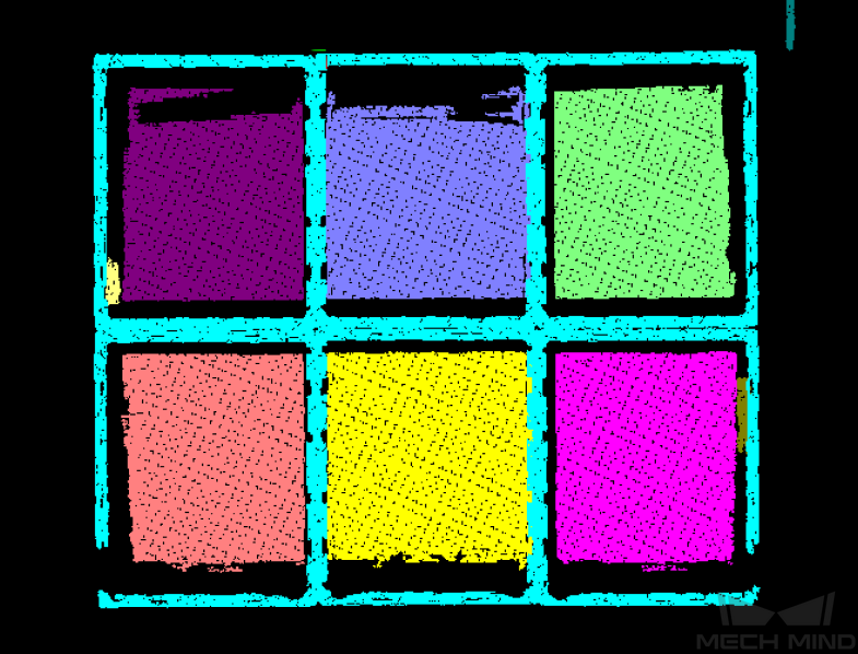
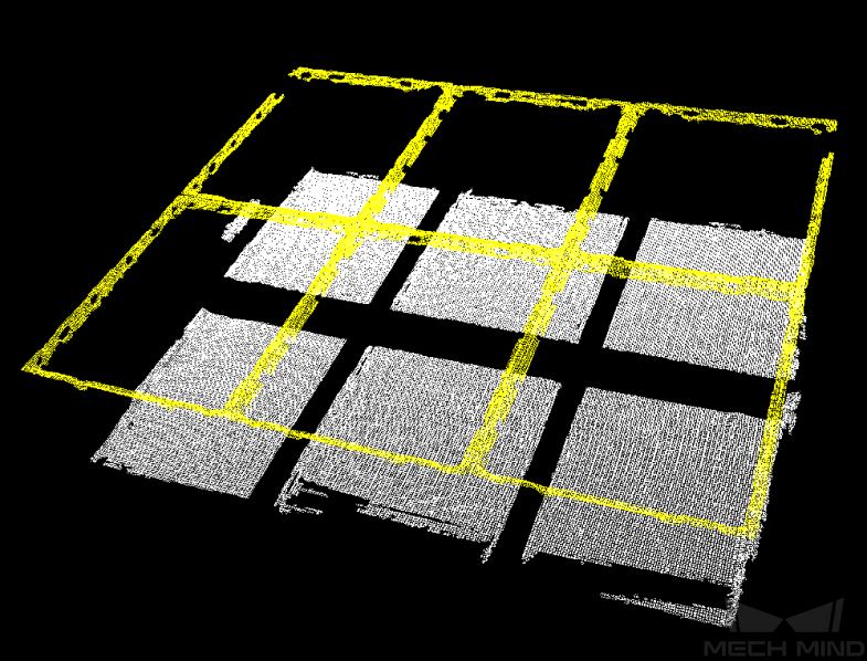
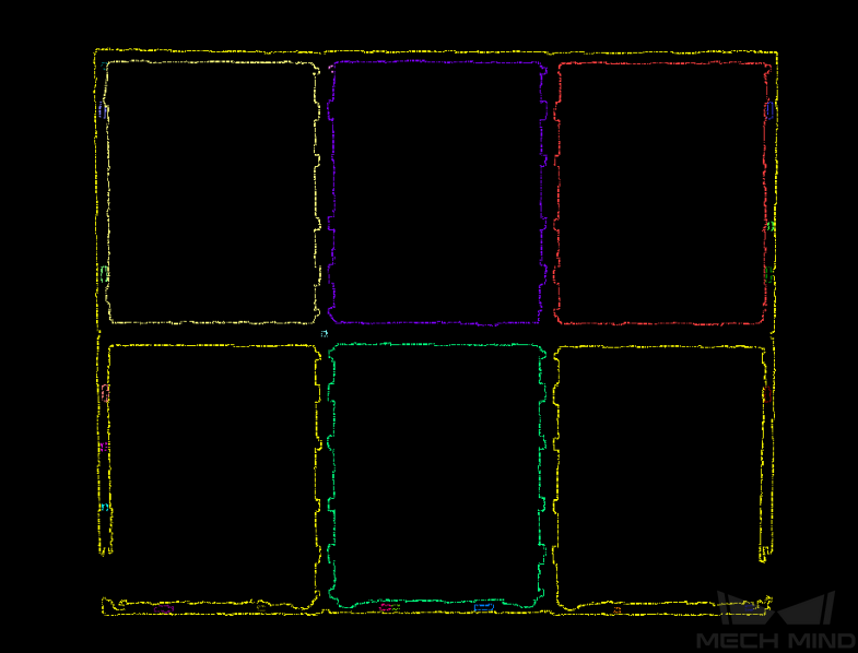
Problem description: The Estimate Point Cloud Edges by 2D Method Step extracts very few point clouds of the inner edges of turnover boxes.
Solution: Set appropriate values for the Morphological Operation Settings parameters of the Estimate Point Cloud Edges by 2D Method Step. For example, the extracted edge point cloud when Dilation Kernel Size is 21 pixels is shown in the left figure below, and the extracted edge point cloud when Dilation Kernel Size is 5 pixels is shown in the right figure below.

Problem 2
Problem description: There are deviations in the pose matching results.
Solution: First, check the quality of the point cloud input to the 3D Matching Procedure. If the point cloud quality is poor, you should adjust the parameters of the Point Cloud Preprocessing procedure so that all the point clouds of the inner edges of turnover boxes can be extracted. Then, adjust the parameters of the 3D Coarse Matching V2 and 3D Fine Matching Steps. It is recommended to first adjust the Expected Point Cloud of Sampled Model and the Voxel Length parameters (visible when Parameter Tuning Level is set to Advanced) of the 3D Coarse Matching V2 Step.
Problem 3
Problem description: The edge point clouds cannot be extracted by the Estimate Point Cloud Edges by 2D Method Step, because the quality of the point cloud is too poor or the top edges of the turnover boxs are blocked by objects inside the boxes.
Solution: Try matching with a full point cloud model.