Create a Project
Set Mech-Viz Execution Path
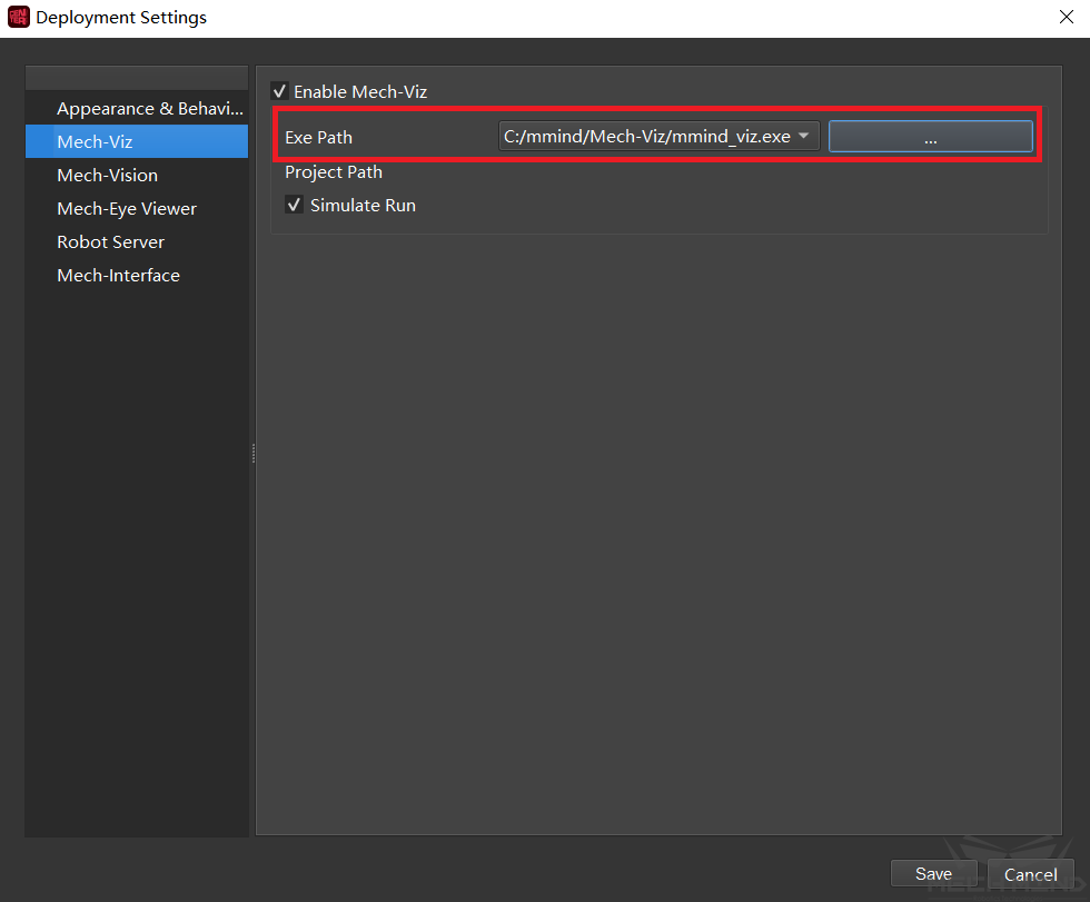
Launch Mech-Center, in Deployment Settings, select Enable Mech-Viz, set the Exe Path, as shown in the screenshot below.
Establish Connection with the Real Robot
Start Mech-Viz from Mech-Center.
In Mech-Viz, select the robot model under Configure Robot in the Robot tab, save the project, and select Autoload Current Project in the bar on the top.
Click Connect Robot in Mech-Center.
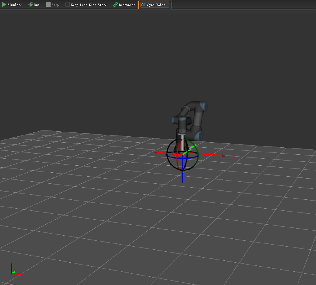
Click Sync Robot to obtain the relative position of the real robot and the scene. At this point, the model(s) of the surrounding object(s) can be imported in the Scene tab based on the on-site circumstances. As shown in the screenshot below.
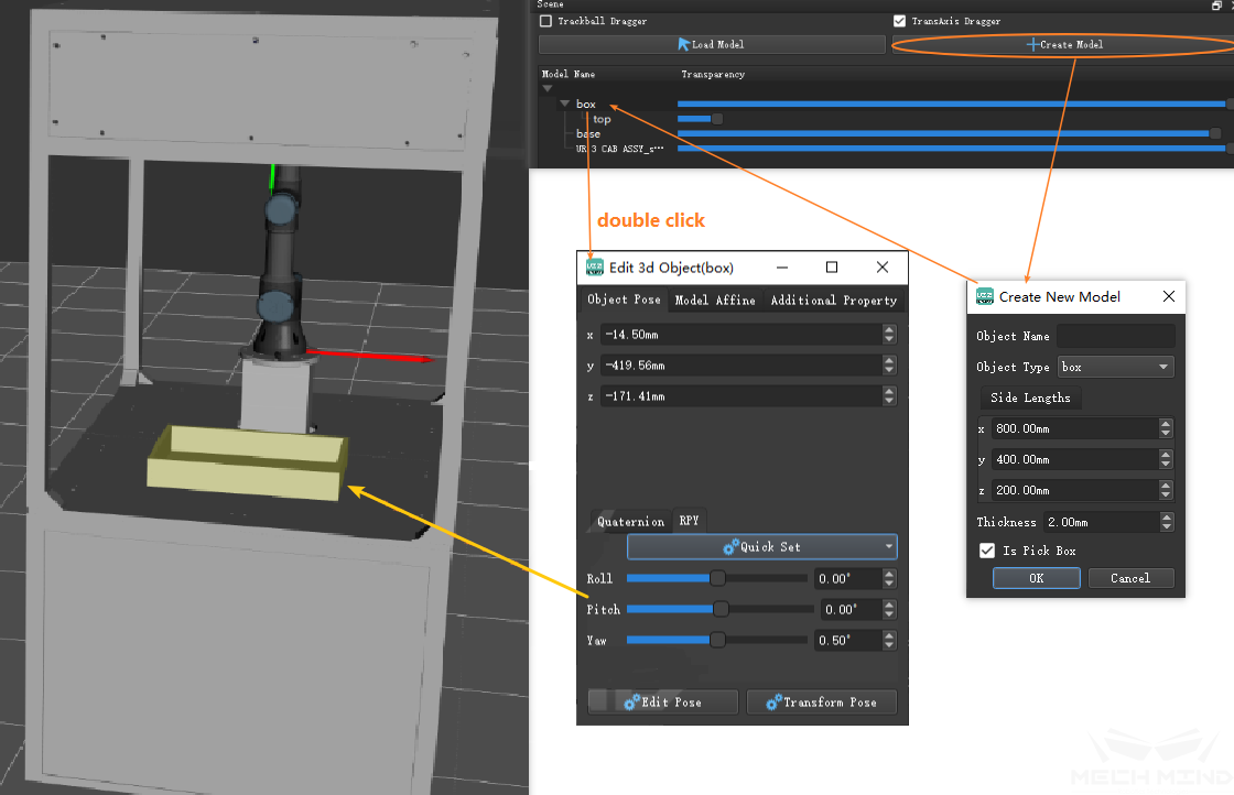
After determining the type and size of an object model, double-click the model name or directly double-click the model in the 3D simulation area to pop up the editing interface to adjust the pose of the model.
Writing a Robot Program
Taking a vision-guided pick-and-place mission as an example, the object to pick is a rectangular parallelepiped, with 180° symmetry around the z-axis, and the end effector is a circular suction cup with 0° symmetry at the pick point.
Set Symmetricity
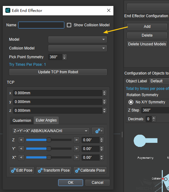
Click Add under End Effector Configuration in the End Effector & Objects tab, set Pick Point Symmetry to 0°; in the same tab, under Configuration of Objects to Pick (For move planning), set the rotational symmetry around the Z-axis (Z Step under Rotation Symmetry) of the target object to 180°.
Write A Simple Teach-In Program
Try to control the robot’s movement through the graphical modules.
As shown in the figure, pull a “move” module from the mission set interface on the left to the programming interface in the middle.
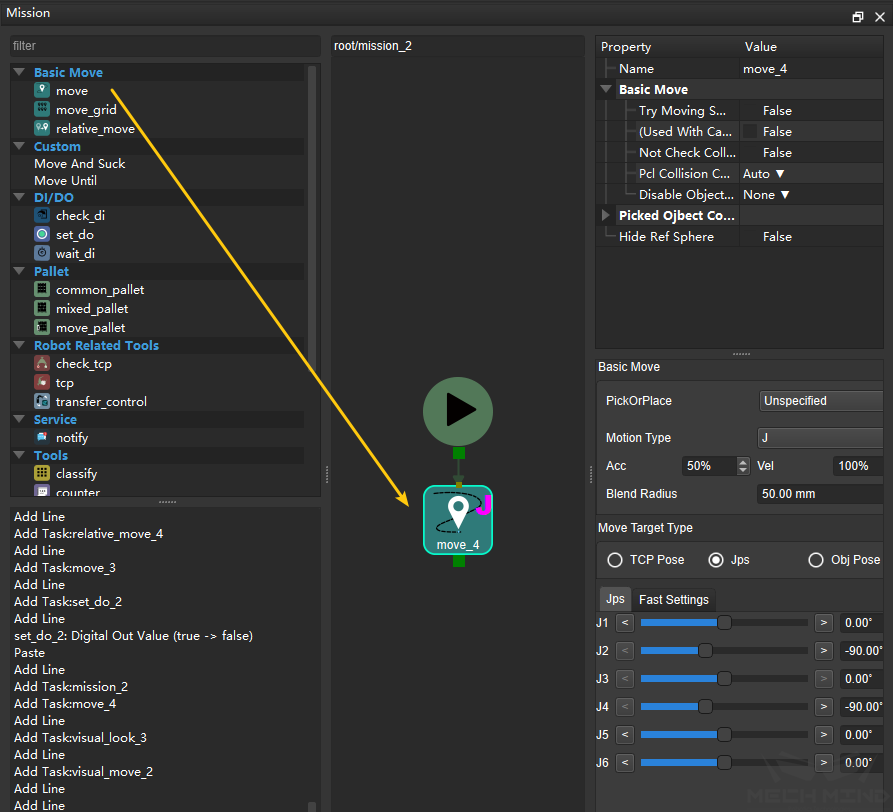
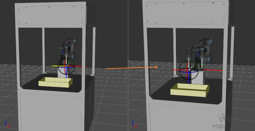
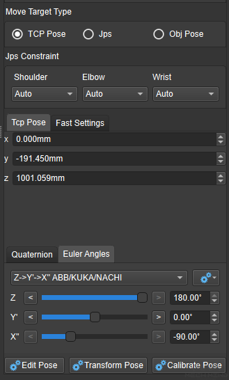
There are many ways to set the pose of the target point. The target pose can be set by dragging in the 3D simulation, or through the parameters on the right.
As shown in the screenshot below.
After connecting the input of the “move” task to the rest of the tasks, the move can be simulated by running the program, i.e., clicking Simulation in the upper left corner.
Tip
The “move” task is usually used to set the initial position, the photo-taking position, and the transition during picking and placing. Normally, to reduce the possibility of singularity, joint motion (J in Motion Type) is selected. In case of too many obstacles in the scene, to prevent collisions of the robot with the surrounding objects, which may result in project failure, more move tasks can be added to add intermediate points, thus exerting more control of the robot’s movement.
Introduce Vision Services
After setting the initial pose, vision services can be introduced.
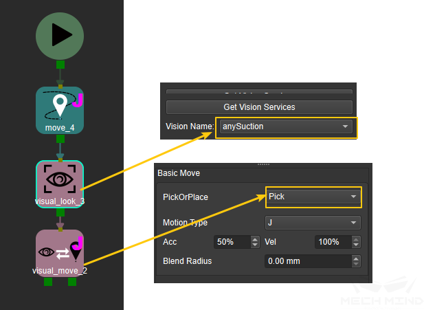
As shown in the screenshot, drag a “visual_look” module and a “visual_move” module into the programming interface and connect;
For the “visual_look” module’s Name under Property on the right, select the name of a vision service registered in Mech-Vision. For the “visual_move” module, select Pick for PickOrPlace under Basic Move on the right.
When the program runs to the “visual_look” task, it will call the corresponding Mech-Vision project, which takes a picture and return the point cloud and vision results; when the program runs to the “visual_move” task, it takes the vision service results from the most recent “visual_look” task to control the robot to move along the planned trajectory.
A “visual_move” module has two output ports. When there are vision service results and there is at least one appropriate pick point, the output is made through port 1, and when there is no appropriate pick point, the output is made through port 2.
Build a Complete Project
With “visual_look” and “visual_move” tasks as the core of a project, some “move” and “relative_move” tasks can be applied to add intermediate points as appropriate based on the vision service results and the surrounding objects in the scene.
Of a “visual_move” module, at port 1, modules for pick-and-place tasks such as palletizing can be added, and at port 2, a “visual_look” module can be added by need to capture images again or modules for other processings can be added.
For the mission (the group of modules that collectively serve one particular task, added via “mission” under Topology) that complete picking or placing, the end effector is controlled by adding a “set_do” module that sends digital output.
Applications including depalletizing, palletizing, feeding, sorting, etc. are implemented through the cycling of the pick-and-place process described above.
The following figure shows a simple and complete example project. Different modules can be selected to complete the required functions by actual needs.
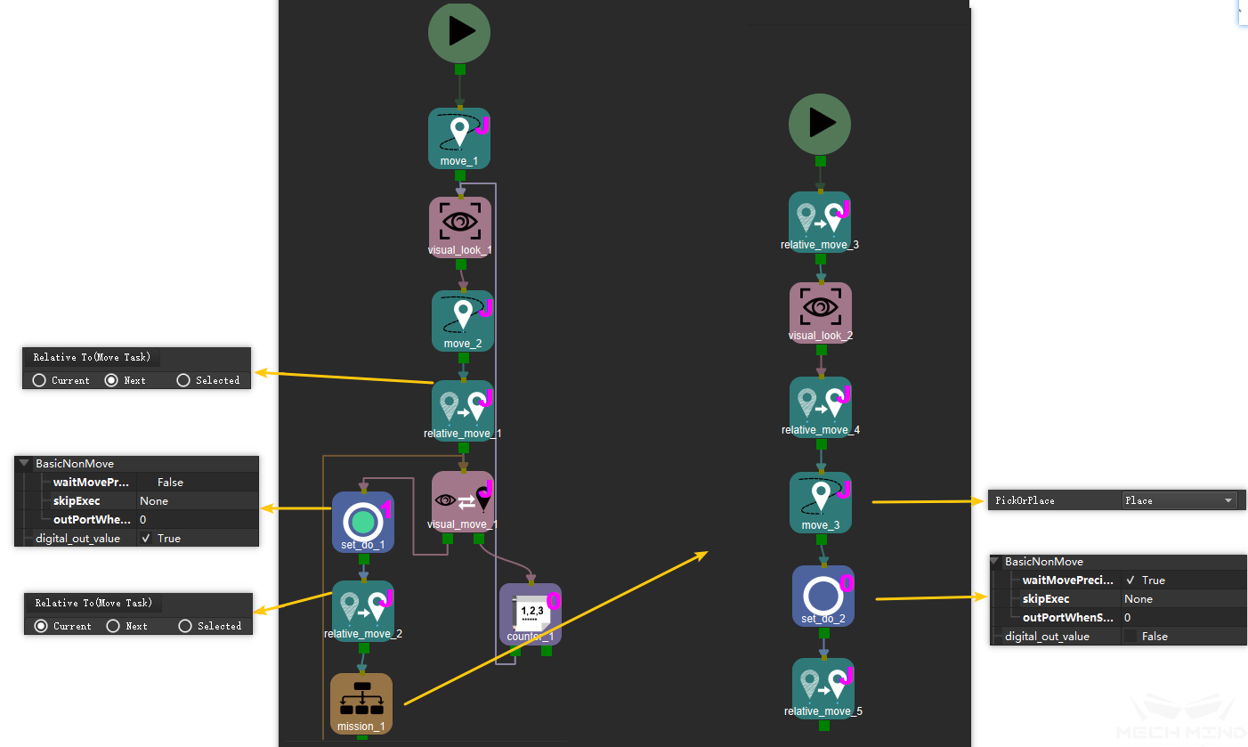
Parameter adjustment and optimization:
To ensure the readability of the graphical program, please put modules serving one task such as picking into a group, contained by a “mission” module found under Topology in the mission set interface.
Please add intermediate points as appropriate to prevent collisions or drastic overturning of the robot;
For a “set_do” module, the entire movement can be smoother by setting Wait Move Precisely to
Falseto ready the end effector before the robot reaches the picking pose.Before and after picking, by adding a “relative_move” task and setting the Motion Type after picking to L (straight-line move), collisions with surrounding objects, such as the boxes around the target object, can be better avoided.
If no vision service result is returned or no pick point is found, the visual recognition task should be re-run. If the results are still invalid, the project should be terminated.
In the pick-and-place mission set, add vision service modules again to take vision results when the robot is placing the object so that the robot can start the next round of pick-and-place missions to shorten the cycle time.
Taking into consideration the symmetry of the target object, please set PickOrPlace of the “move” task to Place and set the Move Target Type to Obj Pose to remove the relative position binding of the object and the robot TCP。
Generally, during the move to a fixed point, the speed can be appropriately increased to optimize the cycle time, while the relative movement before and after the picking should be relatively slow to ensure the stability of the picking.
Run the Project
Attention
Mech-Viz 1.4.0 will perform a version compatibility check when running the project. It is recommended to use Mech-Vision and Mech-Center 1.4.0 with Mech-Viz 1.4.0.
If the version of Mech-Vision or Mech-Center used is lower than v1.4.0, a risk warning prompt window will pop up when running the project.