Your First Pick
After Mech-Mind Vision System is constructed, you can start deploying the vision solution for the first pick.
Create a Solution
Open the Mech-Vision software. The Welcome to Mech-Vision will be prompted.
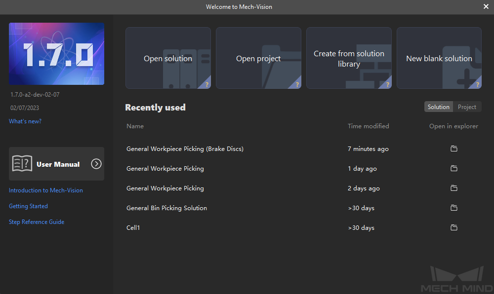
Click the Create from solution library card to open the solution library.
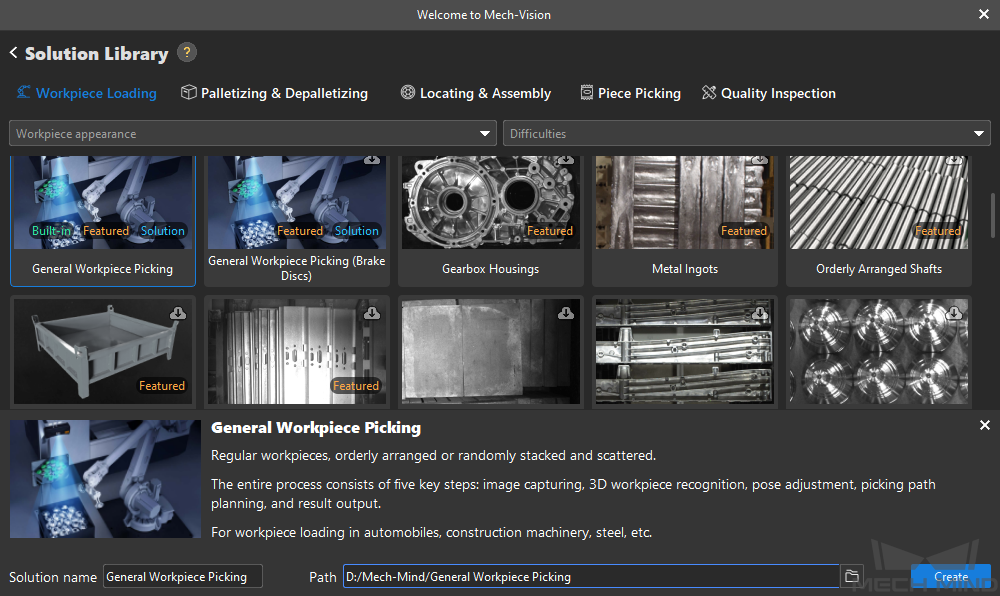
At the bottom of the solution library, click the More link to obtain the latest data of the solution library.
On the Workpiece Loading tab, select the General Workpiece Picking solution, specify the Solution name and Path parameters, and click the Create button.
Note
The software will download the data of the solution from the online solution library.
Click the Learn more button to view the help document of the solution.
In the prompted dialog box, click Yes to confirm downloading the data of the solution from the online solution library.
Wait for the software to download the data of the solution from the online solution library. After the downloading succeeds, the solution will be opened automatically.
Complete Robot and Communication Configuration
To ensure that the vision side and the robot side can communicate normally, you need to:
Complete the robot and communication configuration on the vision side.
Complete the communication configuration on the vision side.
Test that the robot side and the vision side can communicate normally.
Complete the Robot and Communication Configuration on the Vision Side
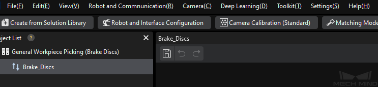
In Mech-Vision, click Robot and Interface Configuration button on the toolbar.
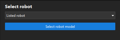
Select the robot.
Click the Select robot dropdown box, and select Listed robot, and then click the Select robot model button.
Click the Brand dropdown box, select “ABB”. Then, at the right panel, select model “ABB_IRB_120_3_0_6” and click the Select button.
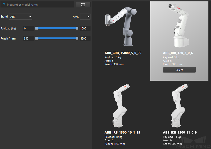
click the Next button.
Configure the TCP/IP Socket communication.
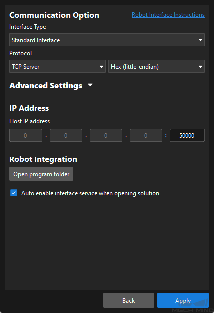
On the Communication Option interface, set Interface Type to Standard Interface, Protocol to TCP Server and HEX-Little endian , set the port of the host IP address to 50000 , and then select the Auto enable interface service when opening solution checkbox.
Tip
Please complete the configuration of the communication mode according to your robot brand.
Click the Apply button.
At this time, the interface service is started automatically. The vision side will function as a TCP/IP server, and listen to TCP/IP requests sent from the robot side on the IPC’s IP address and port 50000.
Complete the Communication Configuration on the Robot Side
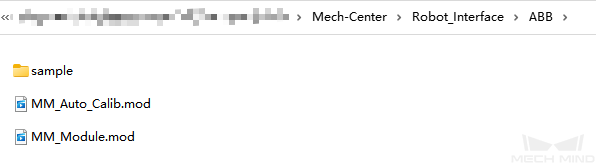
Click the Open program folder button in the previous step to find the Standard Interface communication program, automatic calibration program, and picking example program provided by Mech-Mind.
Note
MM_Module.mod: Standard Interface communication program for the robot.
MM_Auto_Calib.mod: automatic calibration program.
MM_Sample.mod in the sample folder: picking example program.
Complete the robot Standard Interface communication configuration by referring to the Standard Interface Communication section.
After the robot programs or plugins have been installed on the robot, the robot will function as a TCP/IP client and send TCP/IP requests to the TCP/IP server.
Test That the Robot Side and the Vision Side Can Communicate Normally
Tip
For the testing method for other robot brands, please refer to Standard Interface Communication section or the robot user manual.
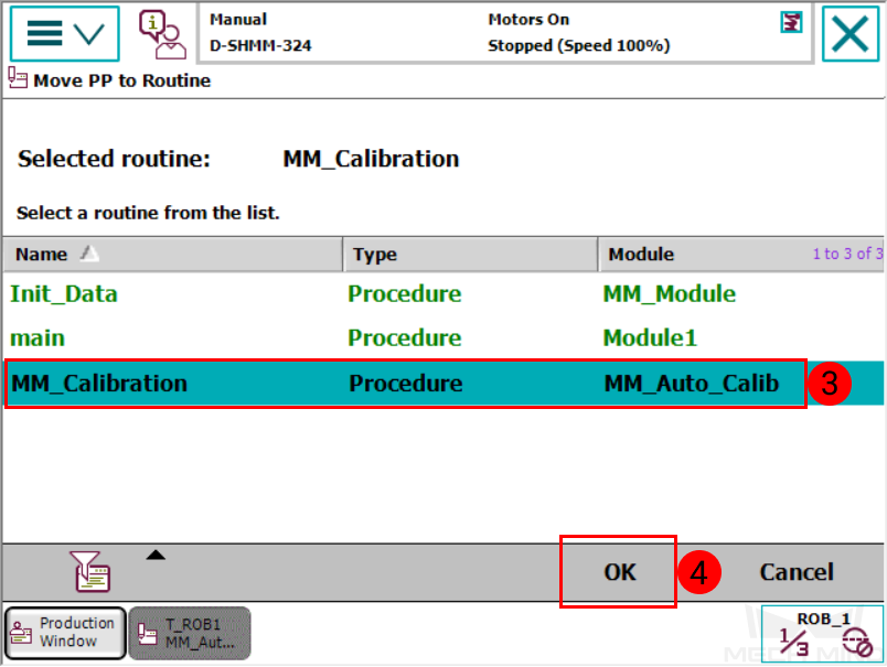
On the teach pendant of the ABB robot, select Debug -> PP to Routine.
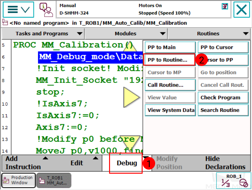
Select MM_Calibration and then press OK.
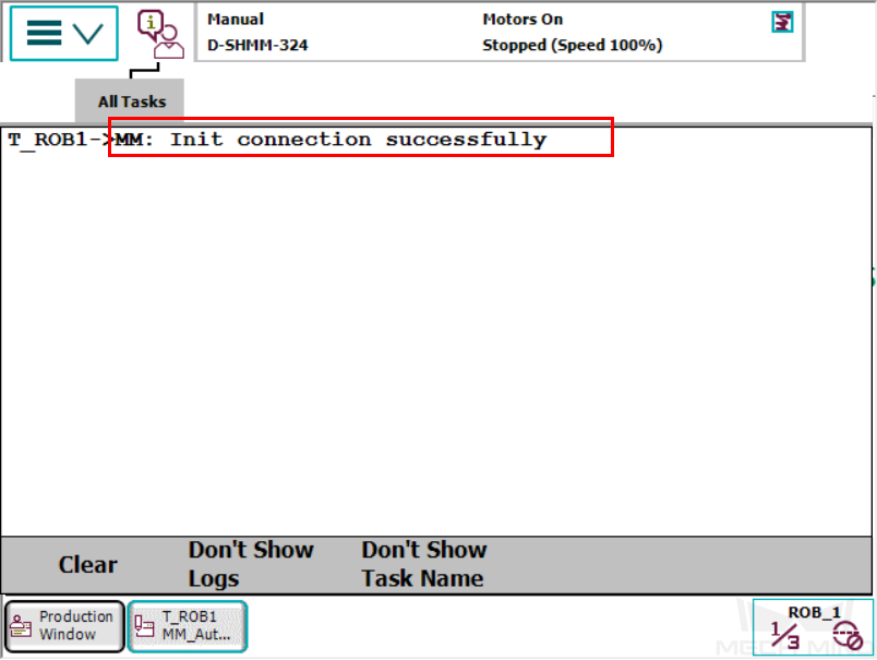
Tap the single-step execution button on the teach pendant to execute the program until the PP moves to line 9.

Confirm that the success message is displayed on the teach pendant: T_ROB1→MM: Init connection successfully.
Complete Robot Hand-Eye Calibration
In this example, you will use the automatic calibration mode to perform the robot hand-eye calibration, establishing the transformation relationship between the camera and robot reference frames.
Pre-calibration Configuration
Open Mech-Vision, and click the Camera Calibration (Standard) button on the toolbar. The Configuration before Calibration window will be prompted.
In the Select how to calibrate window, select the New calibration radio button, and then click the Next button.
In the Select calibration task window, select Hand-eye calibration for listed robot from the dropdown list box, confirm the robot model, and then click the Next button.
In the Select camera setup window, select the Eye to hand radio button, and then click the Next button.
In the Calibration method and robot control window, select Automatic and Standard Interface, and then click the Next button.
In the Interface settings window, click the Start interface service button. The button will turn into Waiting for the robot to connect….
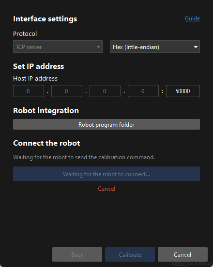
On the robot teach pendant, select the auto calibration program “MM_Auto_Calib”, and teach the start point for the calibration, and run the calibration program. For details, refer to ABB Calibration Program . After the program is started, log message “Entering the calibration process, please start the calibration in Mech-Vision” will be printed in the console log panel of Mech-Vision.
Return to Mech-Vision, confirm that “Connected” status message is displayed in the Connect the robot window, and click the Calibrate button. The Calibration (Eye to Hand) window will be prompted.
Calibration Procedure
Connect to the Camera
In the Connect to camera step, find the camera to connect in the Detected cameras list, and click
 .
.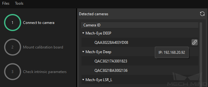
After the camera is connected, click the Capture once or Capture live button.
In the right Image viewer panel, ensure that the captured 2D image and depth map meet the calibration requirements and click the Next button on the bottom bar.
Tip
If the captured image does not meet the calibration requirements, you need to open the Mech-Eye Viewer software to adjust the 2D and 3D scanning parameters and re-capture images.
Mount the Calibration Board
In the Mount calibration board step, select the Standard radio button and the calibration board mode according to its model nameplate in the 1. Select calibration board type area, and click the Confirm button.
Make sure that the calibration board has been attached to the robot flange securely, and then click the Confirm button in the 2. Mount calibration board area.
Make sure that the calibration board is located in the center of the camera’s field of view (the red rectangle), and then click the Confirm button in the 3. Position calibration board into red rectangle area.
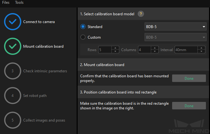
After all operations related to the calibration board are completed, click the Next button on the bottom bar.
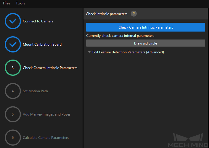
Check Intrinsic Parameters
In the Check intrinsic parameters step, click the Start checking button.
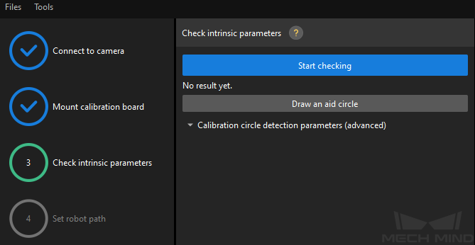
Confirm that the camera intrinsic parameter check passes, and then click the Next button on the bottom bar.
Tip
If the camera intrinsic parameter check fails, adjust detection parameters by drawing aid circles or manually adjusting the detection parameters .
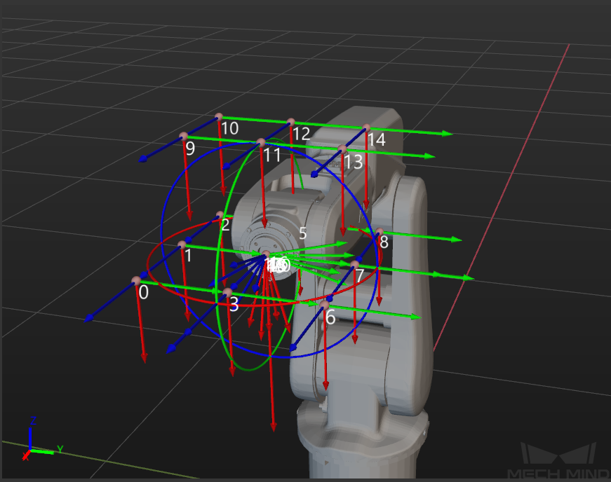
Set the Robot Path
In the Set robot path step, specify the Height span parameter. Please set this parameter according to the working distance range of the calibration in the camera height direction.
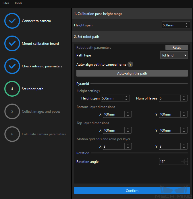
According to the setting of the Height span parameter, set the pyramid and rotation parameters properly and then click the Confirm button.
In the right Scene viewer panel, check the automatically generated robot path will not collide with obstacles in the environment, and then click the Next button on the bottom bar.
Collect Images and Poses
In the Collect images and poses step, select the Save images checkbox.
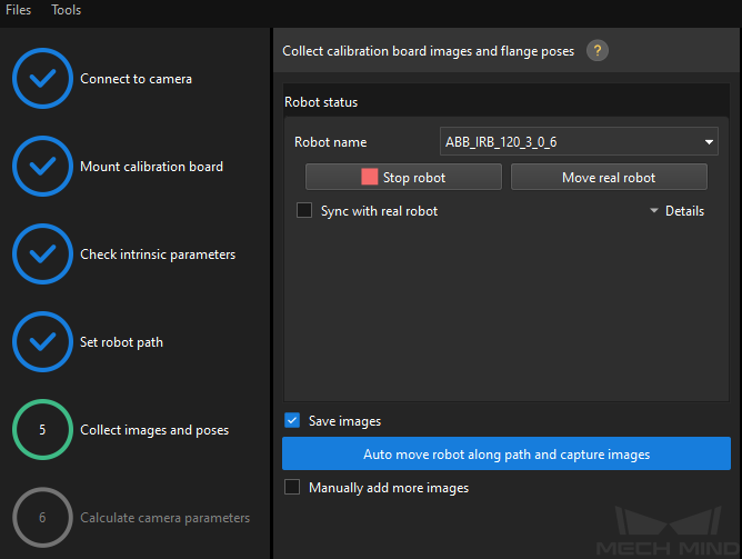
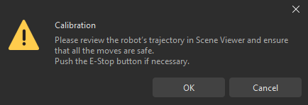
Click the Auto move robot along path and capture images button.
Read the safety window carefully and click the OK button.
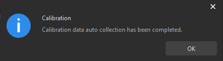
Wait until the robot finishes moving along the preset path and the camera finishes capturing images on all waypoints. Captured images can be seen in the right Calibration images and pose list panel during this process.
After the automatic image capturing finishes, click the OK button in the prompted window, and then click the Next button on the bottom bar.
Calculate Camera Parameters
In the Calculate camera parameters step, click the Calculate camera extrinsic parameters button.
In the prompted window indicating calibration success, click the OK button.
Confirm that the Calibration Accuracy Meets Requirements and Save Calibration Data
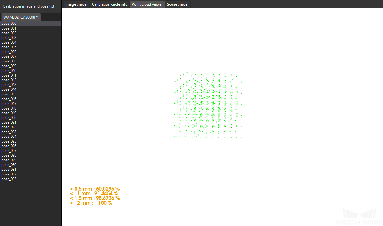
In the Calculate camera parameters step, view the calibration error of point cloud in the right Point cloud viewer panel after the calibration calculation is complete. The error point cloud shows the deviation between the calculated value and the actual value of the circles on the calibration board.
Find the error value with the 100% percentage to get the rough calibration accuracy. For example, the calibration accuracy in the following figure is less than 2 mm.
Confirm that the calibration accuracy meets the project requirements, and then click the Save button on the bottom bar.
In the prompted Save Calibration Files dialog box, click the OK button to save the calibration result to the project folder.
Till now, the robot hand-eye calibration is completed. To enhance the calibration accuracy, refer to the section Calibration Results Analysis.
Debug and Optimize the Solution
In this phase, you need to adjust the project parameters and debugs the project for the typical solution to ensure that the typical solution meets your actual requirements. This section takes the typical solution “General Workpiece Picking” as an example.
Item |
Description |
Step “Capture Images from Camera” |
Disable the virtual mode and select the correct camera. |
Step “3D Workpiece Recognition” |
Make point cloud model ( edge model is recommended) for the workpiece and select it. |
Adjust the region for recognition to improve point cloud processing efficiency and recognition effect. |
|
Adjust 3D matching and output settings. |
|
Step “Adjust Poses” |
Adjust parameters related to pose transformation, adjustment, and sorting. |
Step “Path Planning” |
Configure project resources as required: tool, workpiece, floor, and scene object. |
If collision detection is used, also make and import the visualization model and collision model of the tool, workpiece, and scene objects. |
|
Adjust the workflow and step parameters. |
|
Run simulation and confirm that the planned motion path is collision-free. |
|
Step “Procedure Out” |
Adjust the output ports as required, such as adding label, offset or other keys. |
So far, the Mech-Vision project required by the vision solution has been built. Next, you need to write the robot picking program on the robot side to call the Mech-Vision project to provide a collision-free robot motion path for picking.
Prepare the Robot Picking Program and Run It
In this phase, you need to write a robot picking program, which triggers the Mech-Vision project and obtains the visual points or planned motion path output by the Mech-Vision project through Standard Interface.
In this example, the collision-free robot waypoints are output. You can directly use the Example program provided by Mech-Mind to prepare the picking program.
Before running the picking program, complete the following configuration on the robot side:
Specify the correct Tool Center Point (TCP) for the robot on the teach pendant.
Open the example program on the teach pendant to customize user input:
Specify the IP address of the IPC.
Set the parameter recipe (for various workpiece situations).
Specify the Mech-Vision project ID.
Add intermediate waypoints between the picking point and the placing point according to the actual requirements.
Teach the home position, the image-capturing pose, intermediate waypoints, and placing pose.
Add the gripper logic of picking the workpiece.
Add the gripper logic of placing the workpiece.
Define the Z-offset distances from the picking/placing pose.
After completing the above configuration, run the robot picking program on the teach pendant to start the first pick.
So far, you have successfully experienced the whole process of a Mech-Mind Vision System application, from system construction to solution deployment, and to robot picking. Next, you can further optimize your application and put it into production. For more information, please refer to Application Guide.