Construct Mech-Mind Vision System
Check Package Contents
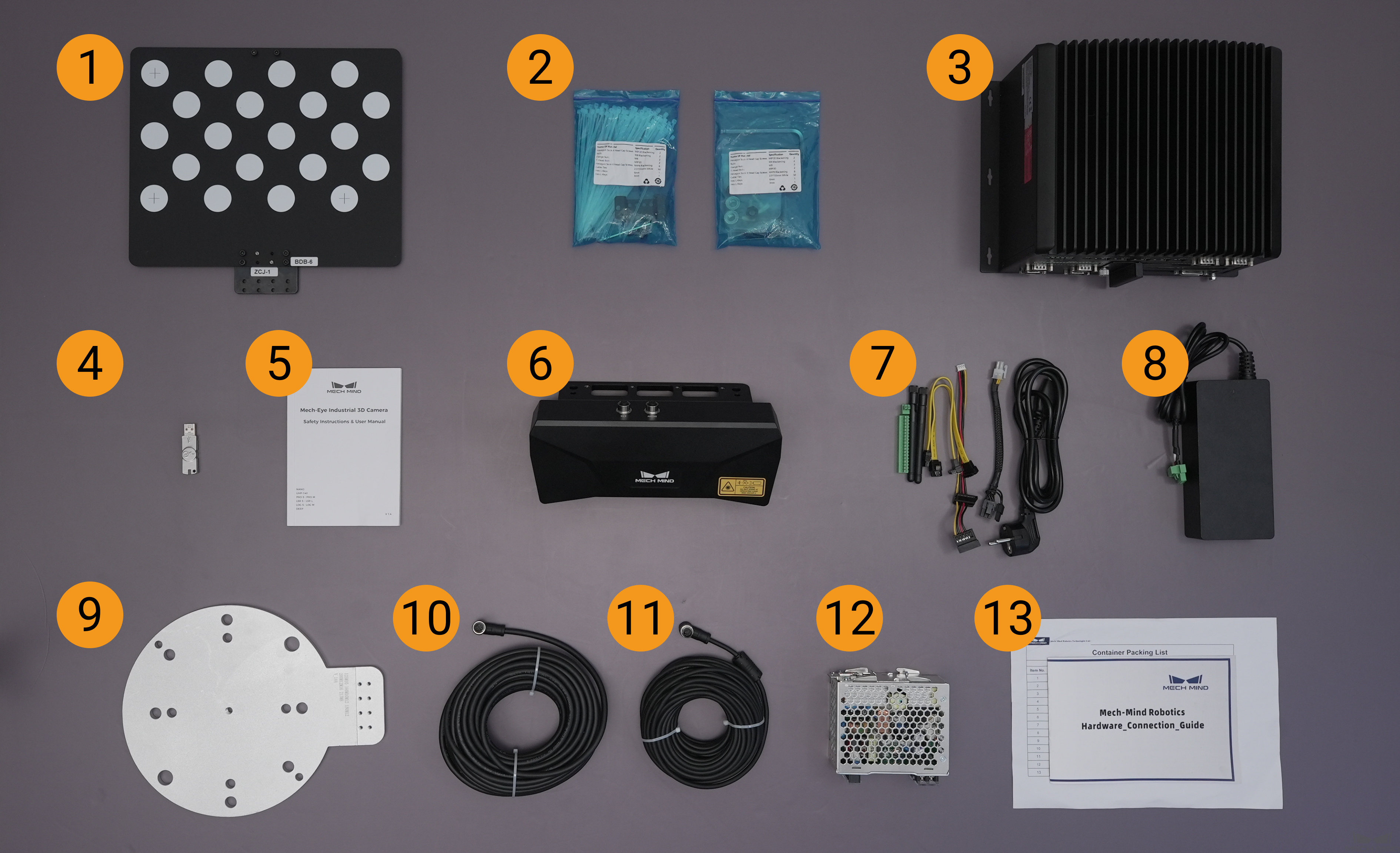
Please make sure that the package is intact when you receive it.
Check according to the Package Contents list in the package to ensure that no devices or accessories are missing or damaged.
No. |
Name |
Function |
1 |
Calibration board |
Calibrate the camera |
2 |
Camera accessory box |
Mount the camera |
3 |
IPC (Industrial Personal Computer) |
Provide Mech-Mind Software Suite |
4 |
License dongle |
License Mech-Mind Software Suite |
5 |
User manual |
Mech-Eye Industrial 3D Camera User Manual |
6 |
Mech-Eye Industrial 3D Camera |
Capture images |
7 |
HDMI cable |
Connect the monitor and IPC |
8 |
IPC adapter |
Supply power to IPC |
9 |
Flange adapter |
Connect the calibration board to robot flange |
10 |
DC power cable (camera) |
Connect the camera and DIN rail power supply |
11 |
Ethernet cable |
Connect the camera and IPC |
12 |
DIN rail power supply |
Supply power to Mech-Eye Industrial 3D Camera |
13 |
Package Contents |
List all the devices and accessories in the package |
Hint
The table above is for reference only. Please take the Package Contents list in the package as the final. Contact Mech-Mind if there are any items missing or damaged.
Mount the Camera
It is recommended to mount the camera through the camera bracket, which is already attached to the back of the camera when packaged.
Find the bolts and wrench inside the accessory box.
Tighten the two bolts with the wrench to fasten the camera, as shown below:
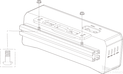
Please remove the screen protector after the camera is mounted.
Tip
If your camera is to be mounted in EIH mode, please refer to Check before Installation for more information.
Mount the IPC (optional)
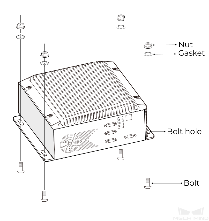
If the IPC needs to be mounted on a rack, please refer to this section for instructions. If not, you can skip this part and place the IPC wherever you find appropriate.
The wrench, bolts, nuts, and gaskets are not included in the package. Please prepare them beforehand.
Place the bolt, gasket, and nut one by one, and Tighten the two bolts with wrench.
Mount the Accessories
For ETH mounting mode, the calibration board should be mounted on the last joint of the robot. Usually the flange adapter is used to connect the board to the robot.
Please fix the flange adapter on the last joint of the robot with bots, gaskets, and buts, and then fix the calibration board on the flange adapter.
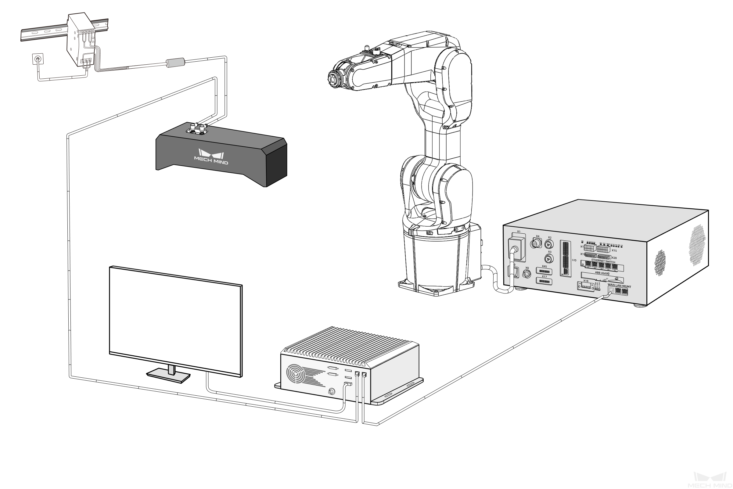
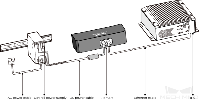
Connect Components of the Vision System
Please refer to this part to connect components of the Mech-Mind Vision System, as shown below:
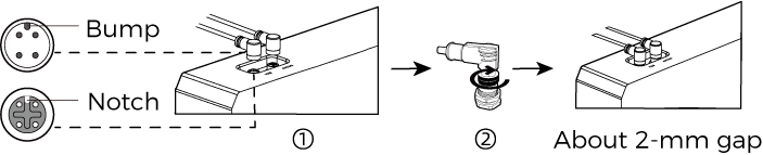
Connect the Camera
Camera connection consists of two parts:
Connect the camera and IPC with the Ethernet cable.
Insert the bump on the M12 connector into the notch of the port.
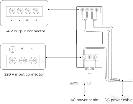
Power the camera with the DIN rail power supply.
The AC power cable has three wires: PE, N, and L. Insert them into the 220 V input connector (
 , N, L) respectively.
Connect DC power cable:
Connect the +V wire to the +V connectors of the 24 V output connectors.
Connect the -V wire to the -V connectors of the 24 V output connectors.
Connect the PE wire to the 220 V input connector
.
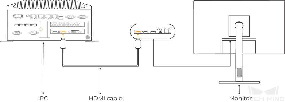
Connect the IPC
Connect the IPC and the monitor (use your own) with the HDMI cable.
Insert one end of the HDMI cable into the HDMI port on the back of the monitor, the other end into the HDMI port of the IPC, as shown below.
Power the IPC with the power adapter.
Insert the power cable of the adapter into the power port of the IPC.
Connect the adapter to power on the other end.
Insert the license dongle.
Insert the license dongle into the USB port of the IPC.
Connect the Robot IPC Controller
Connect the controller to the power supply.
Connect the Network
Connect the Network
Insert the other end of the Ethernet cable connected to the camera into the Ethernet port of the IPC.
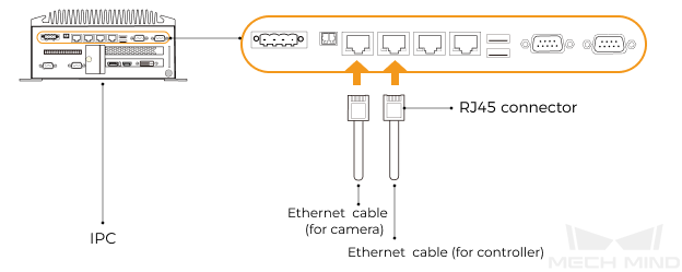
Prepare an RJ45-to-RJ45 Ethernet cable and insert one end of the cable into the Ethernet port of the robot controller and the other end into the Ethernet port of the IPC.
Set IP Address on IPC
Start the IPC and go to and enter the Networking page.
Right-click the Ethernet port connected to the camera/robot, and select Properties.
In the pop-up window, click Internet protocol version 4 (TCP/IPv4) and select Properties.
Tip
The IP addresses of the IPC Ethernet ports should not be set in the same subnet, otherwise IP address conflict may occur.
Set Camera IP Address
Run Mech-Eye Viewer on the IPC.
Hover the cursor on the camera for which you’d like to set the IP address. Click
 to open the window for IP address configuration.
Select Set as Static IP, and select the IP Address Class according to your actual situation. Then, set the IP address and subnet mask for the camera and click Apply.
Tip
The camera’s IP address must be set in the same subnet as the IP address of the IPC Ethernet port connected to the camera.
Set Robot IP Address
Please follow the robot’s user manual to set the robot IP address.
Tip
The robot’s IP address must be in the same subnet as the IP address of the IPC Ethernet port connected to the robot controller.
Check the Network Connectivity between the IPC and the Camera/Robot
Press Window + R to open the Run dialog box.
Type cmd and click OK.
Type ping XXX.XXX.XX.XX in the command prompt window. Press Enter to run the command.
Tip
Replace XXX.XXX.XX.XX with the actual IP address of the camera/robot.
Check whether the returned messages of the command is as follows:
Pinging XXX.XXX.XX.XX with 32 bytes of data:Reply from XXX.XXX.XX.XX: bytes=32 time<1ms TTL=128Reply from XXX.XXX.XX.XX: bytes=32 time<1ms TTL=128Reply from XXX.XXX.XX.XX: bytes=32 time<1ms TTL=128Reply from XXX.XXX.XX.XX: bytes=32 time<1ms TTL=128
Install the Software
Mech-Mind Software Suite is already installed on the IPC purchased from Mech-Mind.
Please check whether the software on the IPC are updated to the latest versions. If not, please refer to the following chapters for instructions on updating the software.
Image Check
After confirming the network connectivity between the IPC and the camera/robot, follow the steps below to confirm that the vision system can operate normally to capture images.
Place workpieces at the center of the camera’s FOV, and ensure that workpieces on the edge and at the top are all within the FOV.
Start Mech-Eye Viewer, connect it to the camera, and perform image capturing.
Check whether the captured images are up to standard.
Tip
If the images are below the required standard, please refer to Mech-Eye Viewer Parameter Adjustment.
Now, you have completed the construction of Mech-Mind Vision System and confirmed that it can operate normally. Next, you can create a vision solution and take your first pick!