Capture Images from Camera
Function
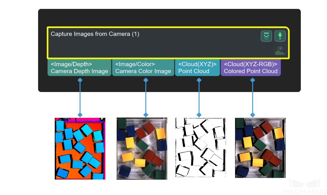
This Step is used to obtain color images, depth maps, and point clouds from a real or virtual camera.
Hint
When this Step is used to connect a DEEP (V4) or LSR (V4) series camera, and the 2D Image Type is set to Internal IR Image, the output “color image” is actually a 2D image (Depth Source). If you want to adjust the 2D image (Depth Source), adjust the 2D Image (Depth Source) Exposure Time of the 2D Image (Depth Source) Exposure Mode in Mech-Eye Viewer.
Usage Scenario
Used as the initial input entry of a vision project, this Step collects data from a Mech-Eye Industrial 3D Camera or third-party camera or acts as a virtual camera for inputting simulated data source.
Input and Output
Parameter Tuning
Camera Settings
- Camera Type
- Description: This parameter is used to select the type of camera in use.Value list:
External2D: External 2D camera
LMI: LMI camera
Mech-Eye (Default value): Mech-Eye Industrial 3D Camera
Mech-EyeTOF: Customized Mech-Eye Industrial 3D Camera
Attention
If the firmware of Mech-Eye Industrial 3D Camera is updated to 2.0.0, it is recommended to use Mech-Vision of version 1.6.2 and above. If you use Mech-Vision 1.6.1 or older versions, the software may crash when you connect the Mech-Eye Industrial 3D Camera in the External2D EBUSCamera category in the Choose the camera and parameter group to use window.
The Virtual Mode is supported only when Mech-Eye camera type is selected.
Tuning recommendation: Different camera types have different parameters. Please adjust according to the actual situation.
Mech-Eye
When the Virtual Mode is disabled, a real camera can be used. When the Virtual Mode is enabled, local data will be used to run the Step. The Virtual Mode is disabled by default.
Use a Real Camera
- Camera ID
- Description: This parameter is used to connect the camera and select the camera calibration parameters.Instruction:
Click Select camera to open the Choose the camera and parameter group to use window.
Select the camera you want to connect, and click
 .
.Note
If the camera is connected successfully,
will become  .
.After the camera is connected successfully, you can click Select from and select the camera calibration parameter group in the drop-down list and then click OK in the lower right corner of the window.
Note
Once the calibration parameter group is selected successfully, the Camera ID, Camera Calibration Parameters, IP, and Port parameters will be automatically filled.
- Camera Calibration Parameters
- Description: This parameter is used to specify the calibration parameter group of the camera.
- IP Address
- Default value: 127.0.0.1Description: This parameter is used to display the IP address of the camera. Please do not modify.
- Port
- Description: This parameter is used to display the port number of the camera. Please do not modify.
Hint
IP and Port are only used for display. Modifying these two parameters will disconnect the camera.
- Timeout
- Description: This parameter is used to set the maximum response timeout period (in seconds) from the camera receives the data to it sends the data to the client. The two types of timeout are as follows:
The camera fails to be connected successfully within the set time.
The camera fails to capture any images within the set time.
Default value: 20 s - Num of Reconnection Attempts
- Description: This parameter is used to specify the maximum number of attempts to reconnect the camera if the camera fails to be connected within the timeout period.Default value: 3
- Camera Config Group
- Description: This parameter is used to select the configuration parameter group of the camera. The camera will capture the data according to the parameters in this parameter group.
Hint
You can add/delete a parameter group in Mech-Eye Viewer.
- Camera Model
- Description: This parameter is only used to display the model of the currently connected camera.
- 2D Image Type
- Description: This parameter is used to set the 2D image type output by the camera.Value list:
Internal IR Image (Default value): 2D images (depth source) whose reference frame is the same as that of the depth map and does not need to be rectified.
External Color Image: 2D images (texture) that should be rectified before use. You should select Rectify to Depth Map when 2D images of this type are output.
Hint
This parameter is only available when a DEEP (V4) or LSR (V4) series camera is used.
- Rectify to Depth Map
- Description: This parameter is used to rectify the reference frame of the external color image to the reference frame of the depth map.Default value: Selected
Hint
This parameter is only available when External Color Image is set as the 2D Image Type.
Background Removal Settings
- Remove Background by Depth
- Description: This parameter is used to remove the information of the background from the depth map.Default value: Disabled
- Depth Background Image File
- Description: This parameter is used to capture or read the depth map of the background.Default value: depth_background.pngInstruction:
Click Select background depth map file to open the Set Background window.
If there is an available image of the background, please see step 2.
If there is not an available image of the background, please see step 3.
Click …, and select the local image map of the background, and click OK to confirm.
Select a camera in the Detected cameras panel on the right, and click
to connect the camera.Note
Once the camera is connected successfully, the depth map obtained from the camera will be displayed in the Image viewer panel on the left.
If you want to update the depth map, click Capture once or Capture live.
If you want to modify the file name of the depth map, enter an Image Name in the text box.
Click OK to finish selecting the depth map of the background.
- Variation of Background Depth
- Description: This parameter is used to compare the depth (mm) of a point in the newly-obtained depth map and the depth of the point in the background depth map. When the difference in depths between the point and its counterpart in the background is less than this value, the point will be considered a point in the background and removed.Default value: 10 mm
- Max Capture Attempts
- Description: This parameter is used to specify the total number of attempts to capture the image if the camera fails to capture any image within the timeout period.Default value: 3Recommended value: 3
- Robot Service Name in Mech-Center
- Description: This parameter is used to specify the robot service name, which should be the same as the name of the robot connected in Mech-Center.Default value: Null
Use a Virtual Camera
When the Virtual Mode is enabled, you will need to adjust the following parameters.
- Camera Calibration Parameters
- Instruction: Once the Data Path is selected, Camera Calibration Parameters will be automatically filled. If there are multiple sets of camera calibration parameters, please select the one you need in the drop-down list.
- Data Path
- Description: This parameter is used to select the folder where images, intrinsic parameters, and extrinsic parameters are stored.Instruction: Click the
 icon on the right and select the folder where images, intrinsic parameters, and extrinsic parameters are stored.Virtual Camera Assistant:
Hint
In the virtual mode, the naming conventions for the images as follows should be followed. The number of the color image should be the same as its depth map counterpart.
Color images: rgb_image_xxxx.jpg
Depth maps: depth_image_xxxx.png
If any one of the following descriptions is true when you select the data path, a Virtual Camera Assistant will be triggered to help you select the image data.
You have not entered a path in the Data Path box.
There are multiple sets of data in the selected folder.
There is no color image, depth map, or intrinsic and extrinsic parameters in the selected folder.
Please follow the steps below to configure in Virtual Camera Assistant:
In the Virtual Camera Assistant window, click
 to select the data path.
Note
Once the path is entered successfully, the Camera ID and Parameter group will be automatically filled.
Click Verify, and a “Camera parameter group updated” message will appear.
Click
to select the folders where color images, depth maps, and the flange pose are stored one by one. Then click Confirm after selecting the data.Hint
The flange pose is needed only when the camera is mounted in eye-in-hand mode.
Lastly, click OK in the pop-up Setup Complete window.
Attention
In the virtual mode, please re-select the data path if there is any modification of the image in the selected data path, or else the new image data cannot be read.
- Play Back Mode
- Description: This parameter is used to specify the order to read the images.Value list:
Sequential (Default value): Read the images in the order of the images in the folder.
Repeat One: Read the current image repeatedly.
Repeat All: Read all images in the order of the images in the folder, and then read them from the beginning after all images are read.
Random: Read images randomly.
Tuning recommendation: Please select the mode according to image reading order you need. - Current Frame Name
- Description: This parameter is used to display the serial number and timestamp of the currently read image.
- Image Name Type
- Description: This parameter is used to select the type of image name output by the Color Image Path port.Value list: Complete Path, File Name, Base NameDefault value: Complete Path
Background Removal Settings
- Remove Background by Depth
- Description: This parameter is used to remove the information of the background from the depth map.Default value: Disabled
- Depth Background Image File
- Description: This parameter is used to capture or read the depth map of the background.Default value: depth_background.pngInstruction:
Click Select background depth map file to open the Set Background window.
If there is an available image of the background, please see step 2.
If there is not an available image of the background, please see step 3.
Click …, and select the local image map of the background, and click OK to confirm.
Select a camera in the Detected cameras panel on the right, and click
to connect the camera.Note
Once the camera is connected successfully, the depth map obtained from the camera will be displayed in the Image viewer panel on the left.
If you want to update the depth map, click Capture once or Capture live.
If you want to modify the file name of the depth map, enter an Image Name in the text box.
Click OK to finish selecting the depth map of the background.
- Variation of Background Depth
- Description: This parameter is used to compare the depth (mm) of a point in the newly-obtained depth map and the depth of the point in the background depth map. When the difference in depths between the point and its counterpart in the background is less than this value, the point will be considered a point in the background and removed.Default value: 10 mm
External2D
- Camera ID
- Description: This parameter is used to connect the camera and select the camera calibration parameters.Instruction:
Click Select camera to open the Choose the camera and parameter group to use window.
Select the camera you want to connect, and click
.Note
If the camera is connected successfully,
will become .After the camera is connected successfully, you can click Select from and select the camera calibration parameter group in the drop-down list and then click OK in the lower right corner of the window.
Note
Once the calibration parameter group is selected successfully, the Camera ID, Camera Calibration Parameters, IP, and Port parameters will be automatically filled.
- Camera Calibration Parameters
- Description: This parameter is used to specify the calibration parameter group of the camera.
- IP Address
- Default value: 127.0.0.1Description: This parameter is used to display the IP address of the camera. Please do not modify.
- Port
- Description: This parameter is used to read the port number of the camera.
Hint
IP and Port are only used for reading. Modifying these two parameters will disconnect the camera.
- Timeout
- Description: This parameter is used to set the maximum response timeout period (in seconds) from the camera receives the data to it sends the data to the client. The two types of timeout are as follows:
The camera fails to be connected successfully within the set time.
The camera fails to capture any images within the set time.
Default value: 20 s - Num of Reconnection Attempts
- Description: This parameter is used to specify the maximum number of attempts to reconnect the camera if the camera fails to be connected within the timeout period.Default value: 3
- Auto Exposure
- Description: This parameter is used to determine whether to enable automatic exposure.Default value: Selected
- Mean Gray Value
- Description: This parameter is used to set the expected gray value of the image. The larger the value, the brighter the image. The smaller the value, the darker the image.Default value: 100
- Exposure Time
- Description: This parameter is used to set the exposure time which affects the brightness of the image. The larger the value, the brighter the image. The smaller the value, the darker the image.Default value: 10
- Max Capture Attempts
- Description: This parameter is used to specify the total number of attempts to capture the image if the camera fails to capture any image within the timeout period.Default value: 3Recommended value: 3
- Robot Service Name in Mech-Center
- Description: This parameter is used to specify the robot service name, which should be the same as the name of the robot connected in Mech-Center.Default value: Null
LMI
- Camera ID
- Description: This parameter is used to connect the camera and select the camera calibration parameters.Instruction:
Click Select camera to open the Choose the camera and parameter group to use window.
Select the camera you want to connect, and click
.Note
If the camera is connected successfully,
will become .After the camera is connected successfully, you can click Select from and select the camera calibration parameter group in the drop-down list and then click OK in the lower right corner of the window.
Note
Once the calibration parameter group is selected successfully, the Camera ID, Camera Calibration Parameters, IP, and Port parameters will be automatically filled.
- Camera Calibration Parameters
- Description: This parameter is used to specify the calibration parameter group of the camera.
- IP Address
- Default value: 127.0.0.1Description: This parameter is used to display the IP address of the camera. Please do not modify.
- Max Capture Attempts
- Description: This parameter is used to specify the total number of attempts to capture the image if the camera fails to capture any image within the timeout period.Default value: 3Recommended value: 3
- Robot Service Name in Mech-Center
- Description: This parameter is used to specify the robot service name, which should be the same as the name of the robot connected in Mech-Center.Default value: Null
Mech-EyeTOF
Please contact Mech-Mind Technical Support for assistance in using the parameters of this mode.