Build the Mech-Vision Project
This section describes how to build a Mech-Vision project used for loading crankshafts.
Project Framework
The project framework of a Mech-Vision project used for loading crankshafts is shown below.
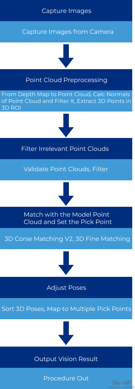
Capture Images: The camera will capture the image of the workpiece and obtain the corresponding color image and depth map.
Point Cloud Pre-processing: The depth map will be converted to point cloud. In order to avoid interference from the background or irrelevant point clouds, the outliers can be deleted.
Filter Irrelevant Point Clouds: In order to increase the project processing speed, point clouds with the number of points that is not in the set threshold can be filtered.
Match with the Point Cloud Model and Calculate the Pick Point: The point cloud after processing will be matched with the point cloud model to recognize the pickable objects in the scene and therefore the pick points can be obtained. You should prepare a point cloud model file and geometric center file for this procedure.
Adjust Poses: Once the pick points are obtained, the reference frame of the pick points should be converted from the object reference frame to the robot reference frame to facilitate picking.
Output Vision Result: After the reference frame of the pick points is converted, the vision results will be sent to Mech-Viz or Mech-Center via the Send Point Cloud to External Service Step.
Build the Project
After a new project is created and saved, you can start to build the project.
Capture the Image
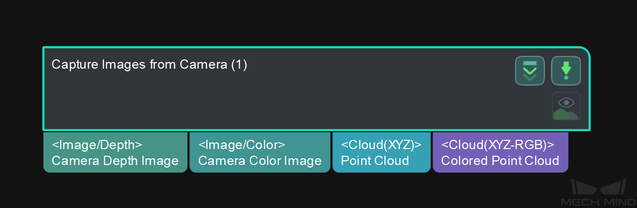
Add the Capture Images from Camera Step that is used to trigger the camera to capture images and obtain color images and depth maps.
Attention
Before adding this Step, please make sure that the camera has been mounted properly and it is connected to the IPC, and you have completed the image capturing test and robot hand-eye calibration.
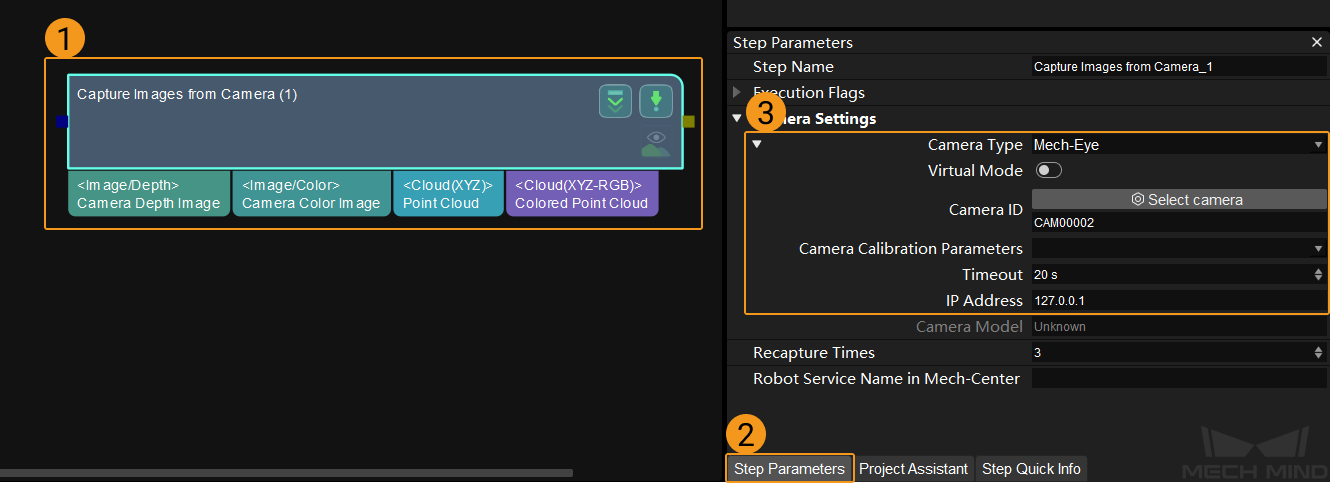
Once this Step is added, you need to connect a real camera. Select the Step and click the Step Parameters tab. Set the Camera Type, Camera ID, Camera Calibration Parameters, and the IP Address in the Step Parameters panel.
Point Cloud Pre-Processing
Add the Point Cloud Preprocessing Procedure.
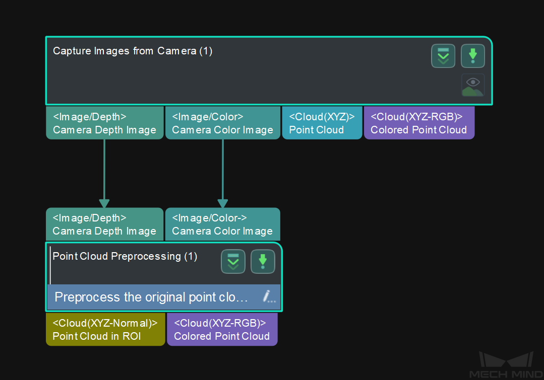
Double-click the Procedure to view the Steps it contains, which are From Depth Map to Point Cloud, Calc Normals of Point Cloud and Filter It, and Extract 3D Points in 3D ROI.
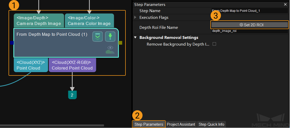
The From Depth Map to Point Cloud Step can convert the depth map obtained from the camera to point cloud.
In order to avoid interference from irrelevant point clouds and shorten the processing time of subsequent Steps, you should select an ROI (Region of Interest) in the 2D image.
Select the Step first, and click Step Parameters, and then click Set 2D ROI. Please refer to Instructions for Setting 2D ROI for detailed instructions.
The Calc Normals of Point Cloud and Filter It Step can calculate the normals of every point in the point cloud, and make the point cloud only with the position information to point cloud with normals.
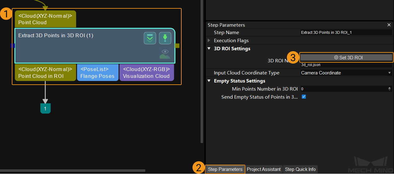
The Extract 3D Points in 3D ROI Step is used to set an ROI in the 3D space. Point clouds within the ROI will be kept or else will be removed, and therefore the interference from point clouds in the background can be reduced.
Select the Step first, and click Step Parameters, and then click Set 3D ROI. Please refer to Instructions for Setting 3D ROI for detailed instructions.
Attention
If you want to send the point cloud to Mech-Viz for debugging or visualization, please connect the Send Point Cloud to External Service Step after this Procedure.
Filter Irrelevant Point Clouds
In order to increase the project running speed and filter irrelevant point clouds, please add the Filter Out Point Clouds That Exceed The Limit Procedure.
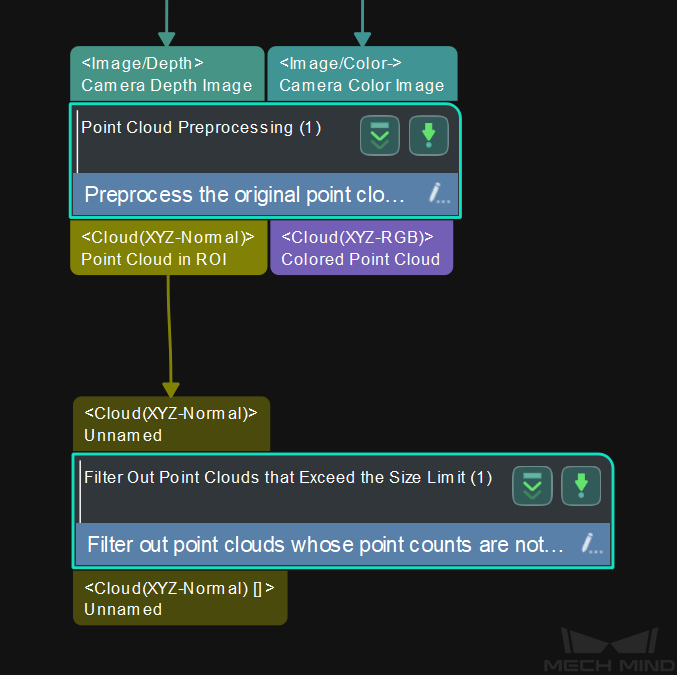
Double-click to view the Steps in the Procedure, which are Validate Point Clouds and Filter.
The Validate Point Clouds Step is used to determine whether the point cloud meets the requirement according to specified rules, e.g., the number of points threshold.
The Filter Step is used as a general list filter. It matches the elements in the input list with True/False in a Boolean list, and outputs the elements corresponding to True.
Match with the Point Cloud Model and Set the Pick Point
Add the 3D Matching Procedure.
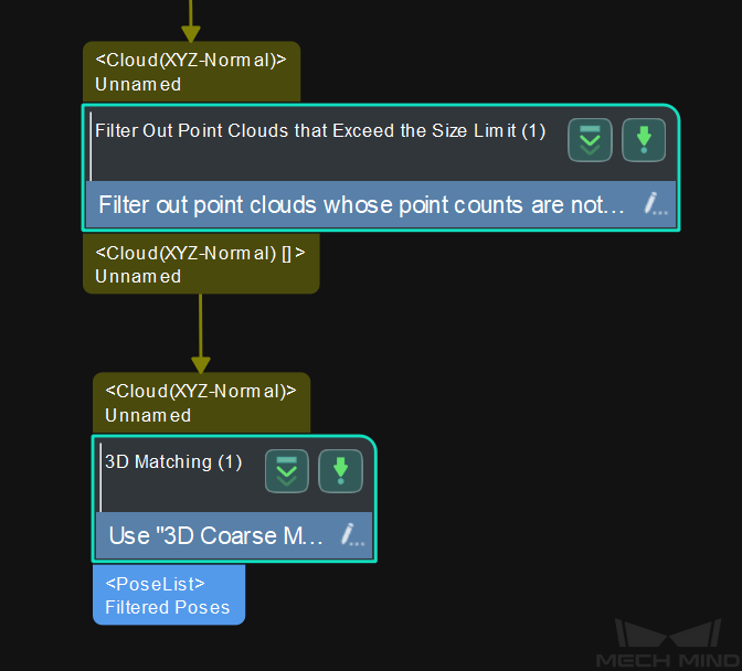
Double-click to view the Steps in the Procedure, which are 3D Coarse Matching V2, 3D Fine Matching, and Remove Overlapped Objects.
The 3D Coarse Matching V2 Step coarsely matches the point cloud model with the input point cloud with normals. Once a feature matching result is obtained, the Step generates the corresponding object geometric center and pick point based on the matched position.
Select the 3D Coarse Matching V2 Step first, and click Step Parameters, and then click
 . Select the model file and geometric center point file to import.
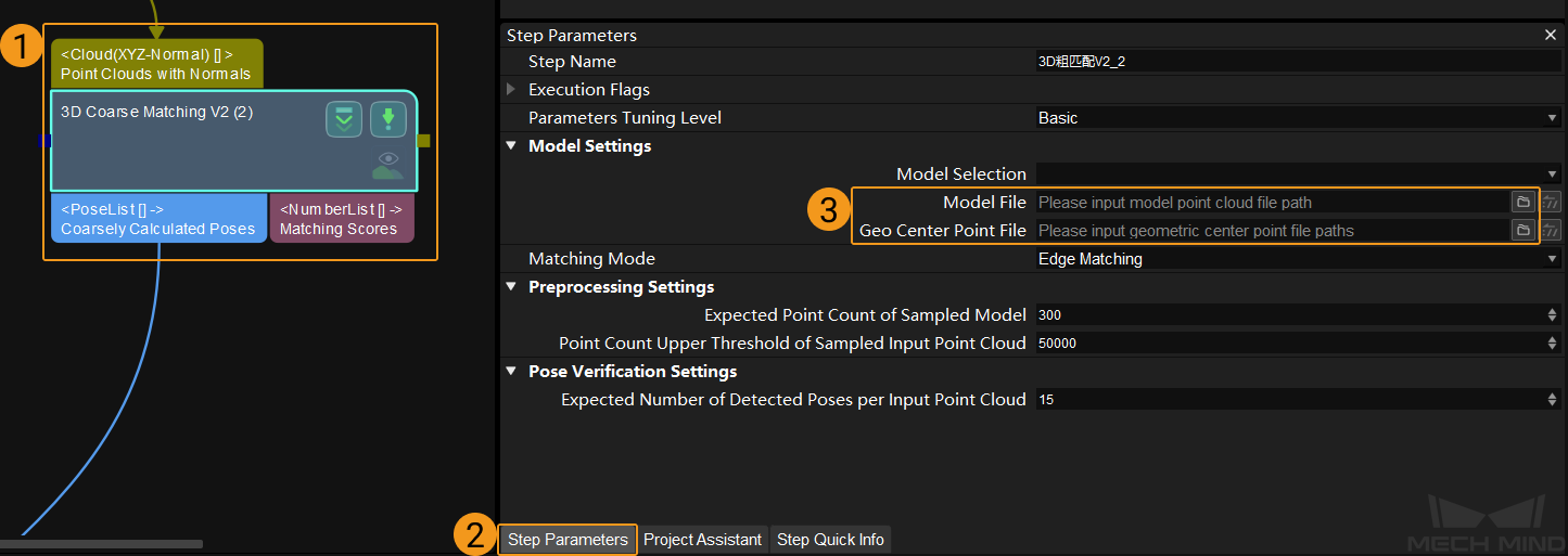
Hint
Please refer to Matching Model and Pick Point Editor to learn about creating the point cloud model file and geometric center point file.
The 3D Fine Matching Step can perform more precise matching calculation on the result from 3D Coarse Matching V2 and obtain a high precision matching result. Also, geometric centers and pick points with a higher precision can be obtained.
Hint
The method to import the model file and geometric center point file in 3D Fine Matching is the same as that of 3D Coarse Matching V2.
Regarding the parameter tuning, you can adjust the Sampling Interval in this Step first according to actual situation. The smaller the value, the more point clouds will be sampled and the higher the accuracy of the model matching. Afterwards, you can adjust the Standard Deviation. Please refer to 3D Fine Matching for detailed information.
The Remove Overlapped Objects Step can remove the poses of overlapping objects according to specified rules.
You can adjust the Overlap Ratio Threshold to adjust the stringency of determining overlapping objects. The higher the threshold, the object is less likely to be determined as overlapping; the lower the threshold, the object is more likely to be determined as overlapping.
Adjust Poses
Sort 3D Poses
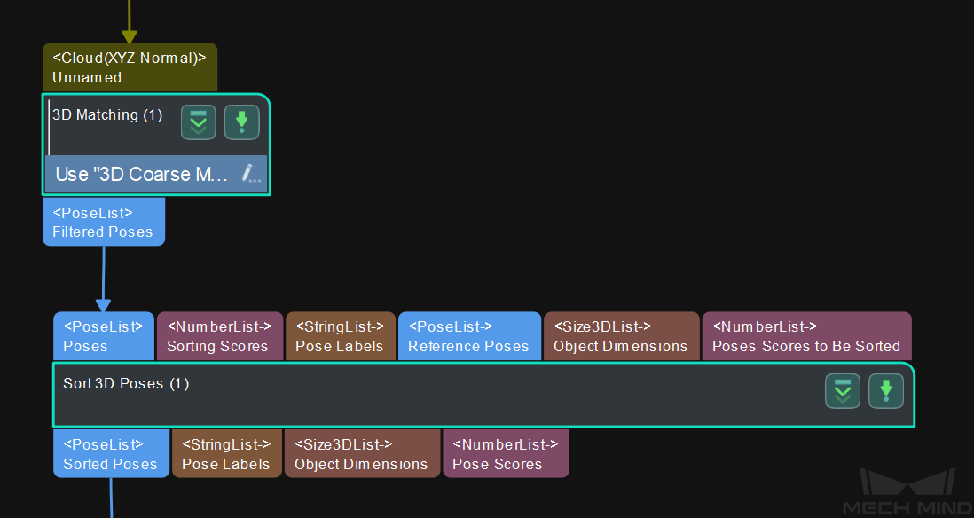
Once the precise poses are obtained from 3D Fine Matching, the poses need to be transformed.
Add the Sort 3D Poses Step, which is used to convert the input poses in the camera reference frame to the robot reference frame. This Step should follow the 3D Matching Procedure. Please select a Sort Method in the Step Parameters according to actual situation.
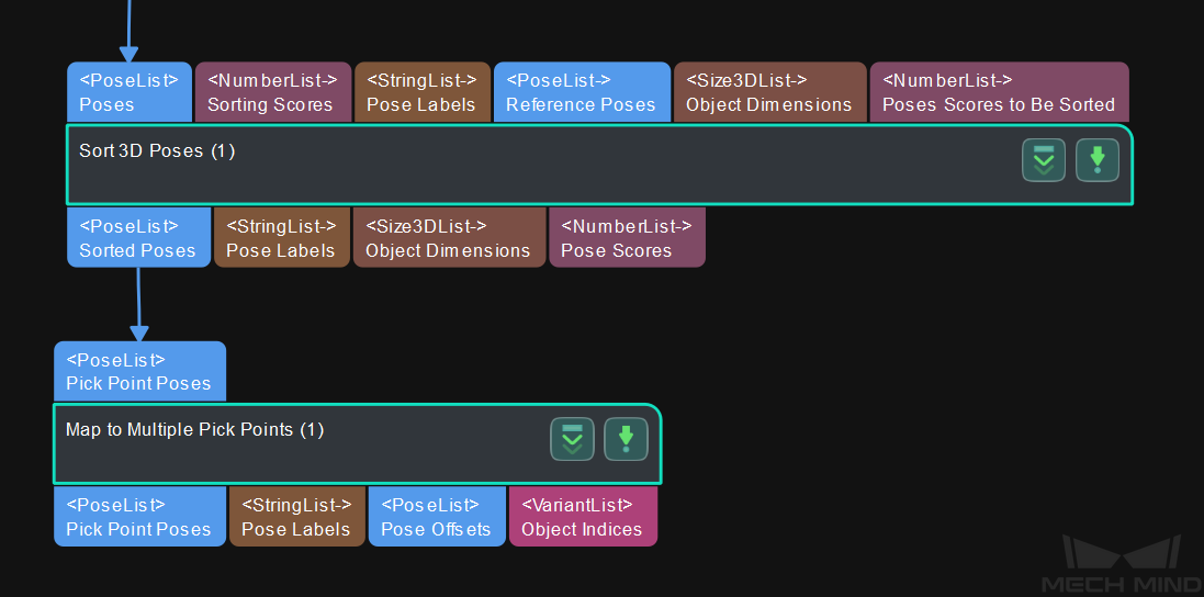
Map to Multiple Pick Points
If the pick point does not coincide with the geometric center point, or there are multiple pick points on the object, you should use the Map to Multiple Pick Points Step to add multiple pick points that can be sent to the robot control software.
Please add this Step after Sort 3D Poses.
Output Vision Results
In order to send the output data to Mech-Center, which will further send the data to software and hardware that need the data, you should add the Procedure Out Step after the Transform Poses Step.
Now you have completed the building of a Mech-Vision project for crankshaft loading. You can use the shortcut keys Ctrl + S or select in the Menu Bar to save the project.
Run and Debug the Project
Once you complete building the project, you can run and debug the project.
Tip
If you want to save the image data and Step parameter settings when running the project, you can connect a Save Images and Step Parameters Procedure after the Capture Images from Camera Step out of the main workflow.