Build the Mech-Viz Project
This section describes how to build a Mech-Viz project used for loading crankshafts.
Project Framework
The project framework of a Mech-Viz project used for loading crankshaft is shown below.
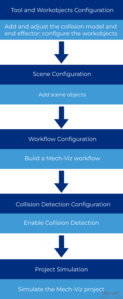
Tool and Workobjects Configuration: You should configure the tool to display the end effector model in the 3D simulation area. The end effector model can be used in the collision detection. You should also configure the workobjects to facilitate the path planning.
Scene Configuration: You can configure the scene to make the scene in the 3D simulation area closer to the actual one, which is conducive to planning a more appropriate path.
Workflow Configuration: The configuration of the workflow is the core of a Mech-Viz project. You can drag the Steps from the Workflow panel to the graphical programming workspace to connect the Steps, and then configure the parameters to implement their pre-defined functions.
Collision Detection Configuration: To prevent the robot from colliding with the bin or other obstacles and ensure that the project runs continuously, you should configure the collision detection settings.
Simulation: Once you have completed all the above configurations, you can simulate the project to check whether it works as expected.
Tool and Workobjects Configuration
After you have imported a robot model, you should configure settings in the Tools and Workobjects panel. To be more specific, you should add the collision model and end effector model, and adjust the tool center point (TCP).
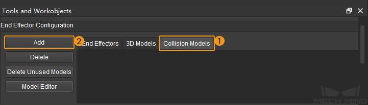
Add and Adjust the Collision Model
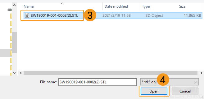
In the Tools and Workobjects panel, click , and select the model you prepared in the pop-up End Effector Collision model file window.
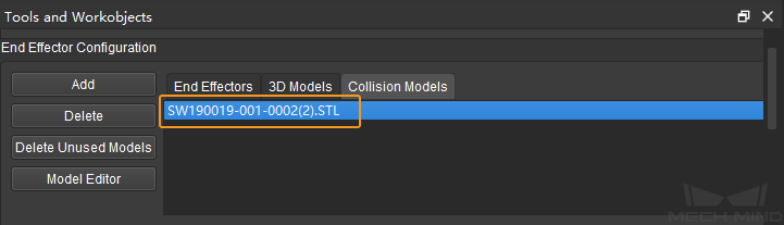
Select the added collision model to visualize it in the 3D simulation area.
The position of the model as shown in the above figure is right. Sometimes, the position of the imported model may be wrong and need to be adjusted.
Add an End Effector
Instruction |
Illustration |
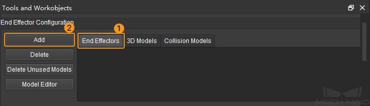
Click End Effectors and click Add. |
|
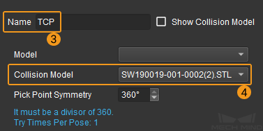
Name the end effector and select the collision model you want to add. |
|
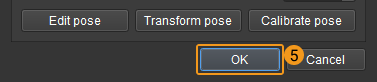
Click OK to save settings. |
|
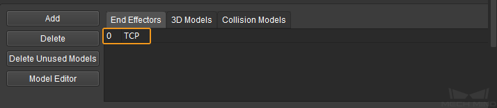
Once you have completed setting, the name of the added model will be displayed in the end effector list. |
|
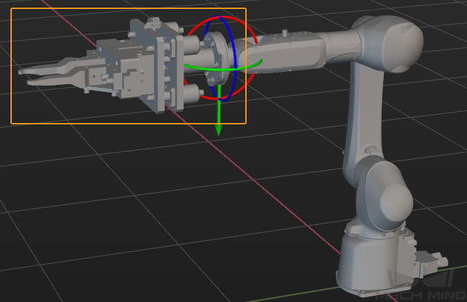
Adjust the TCP
The TCP is represented by the center of the pose manipulator. The TCP should coincide with the end of the robot tool used in the project. Please refer to Adjust the Position or Size of the Tool Model for detailed instructions on adjusting the TCP.
The TCP after the adjustment is shown below.

Configure the Workobjects
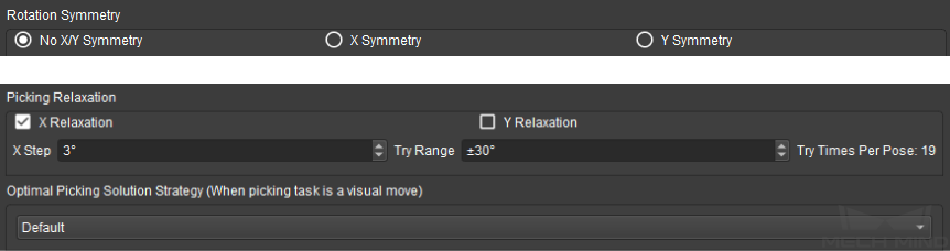
Rotation Symmetry: Since the crankshaft does not have the rotational symmetry, No X/Y Symmetry is selected here.
Picking Relaxation: Since the crankshaft has the curved surface, picking relaxation can be enabled. Select X Relaxation, and set the X Step to 3° and Try Range to ±30°.
Optimal Picking Solution Strategy: In terms of crankshaft picking, Default or Minimum Global Rotation can be used. The picking solution strategy can prevent the robot from rotating meaninglessly after picking the crankshaft, and therefore the crankshaft is less likely to be dropped.
Scene Configuration
If you need to add scene objects in the 3D simulation area to assist path planning, please refer to Scene Objects.
Workflow Configuration
The configuration of the workflow is the core of a Mech-Viz project. You can drag the Steps from the Workflow panel to the graphical programming workspace to connect the Steps, and then configure the parameters to implement their pre-defined functions. The general workflow of this project is described as follows.
Define a “Home position”
The Home position is the start point of the robot motion path. Also, the Home position is a safe position, where the robot is far away from the workobjects and surrounding devices and will not block the camera view.
Since the “Fixed-Point Move” Step can be used to set a target pose in the path and define the motion type for moving, the “Fixed-Point Move” Step is used to set the Home position.
Add an “image-capturing point”
There should be an image-capturing point between the Home position and picking waypoint.
Drag a “Fixed-Point Move” Step to the graphical programming workspace and name it to “image-capturing point”. Connect the entry port of the “image-capturing point” with the “Home position”, and connect the exit port with the “visual_look_1” Step.
Define a “pick point”
The “pick point” should be the pose of the object to be picked. A visual_look Step is added to obtain the vision results, and a visual_move Step is used to guide the robot to move based on the vision results.
Define a “wait after picking” point
After the robot picks the object, it should wait for a while to ensure that the object is grasped firmly.
Define the “relative waypoint”
An appropriate picking motion path should contain a relative waypoint above the object, where the robot will move through it before and after picking. Two “Relative Move” Steps can be added before and after the “picking waypoint” to define the relative waypoint.
Define a “placing waypoint”
Once the robot picks the object, it will move to the placing waypoint defined by you and then place the object.
Drag a “Fixed-Point Move” Step to the graphical programming workspace, and name it to “placing waypoint”.
Define a “wait after placing” point
After the robot places the object, it should wait for a while to ensure that the object is completely detached from the end effector.
Define the “relative placing point”
The placing motion path is similar to the picking motion path described above. Therefore, two “Relative Move” Steps should be added before and after the “placing point” respectively to define the “relative placing point”.
Return to the “Home position”
The robot should return to the Home position after placing the object.
You can create a loop to make the robot return to the Home position and repeat the task.
Simulate
Click Simulate to start simulating the robot motion path.
Collision Detection Configuration
To prevent the robot from colliding with the bin or other obstacles and ensure that the project runs continuously, you should configure the collision detection settings. Please refer to Configure Collision Detection for detailed information.
Project Simulation
Once you have completed the above operations, you can click Simulate to simulate the Mech-Viz project.
Attention
Before simulating the Mech-Viz project, you should open Mech-Center to establish the communication between Mech-Vision and Mech-Viz, and therefore Mech-Viz can receive the scene point clouds from Mech-Vision.