Mech-Viz 1.7.0 Release Notes
This document introduces the new features, improvements, and resolved issues of Mech-Viz 1.7.0.
New Features
New “Welcome” Interface
After the software is started or a project is closed, a “welcome” interface will be displayed. You can create a new project or open a recent project in the “welcome” interface.
New “Resources” Panel
In Mech-Viz 1.7.0, the original “Scene” and “Tools and Workobjects” functional panels are removed. The resources used in the project are re-organized and aggregated in Resources, which is a new tool to manage the project resources.
The aggregated Resources include project, robot, reference frames, tools, floor, scene objects, and model library.
Project: Display the project name, project modification status, and the project autoload status.
Robot: Display the robot model used in the current project.
Reference frames: Aggregate all reference frames in the 3D simulation area.
Tools: For creating and deleting tools and managing the existing tools.
Workobjects: For creating and deleting the workpiece configurations and managing the existing workpieces.
Floor: For adjusting the height of the floor.
Scene objects: For creating and deleting scene objects and managing the existing scene objects.
Model library: For managing all models used in the project. All models should be imported to the Model Library first and then utilized with other functions.
Added “Set as Active Tool”
The concept “active tool” has been introduced in Mech-Viz 1.7.0. The tool set as the “active tool” will be used for path planning when the new round of simulation/execution starts.
When the project is not simulating or running, right-click the name of the tool in the Resources panel and select Set as Active Tool to change the “active tool”.
When the project is simulating or running, you can change the “active tool” by using the “Change Tool” Step.
Added Automatic Layout Feature in the “Predefined Pallet Pattern” Step
The “Predefined Pallet Pattern” Step calculates based on the pallet size, dimensions of the carton, gap width, and limitation of the pallet height to generate a pallet pattern with the most cartons and layers, of which the layout of the odd layer and even layer is also appropriate.
Other New Features
Added “New Project” option in the File menu.
Added robot models for ROKAE SR3 and ROKAE SR4 robots, and generated the corresponding special robot configurations.
You can select multiple Steps and use the shortcut Ctrl + G to pack them as a Procedure, and you can also use the shortcut Ctrl + Shift + G to unpack the selected Procedure.
Added a “Wait Timeout” port to the “Branch by Msg” Step. You can set a timeout period and the Step will take the “Wait Timeout” port to proceed if a timeout occurs.
You can save and import the pallet pattern in the offline mode of the “Mixed Pallet Pattern” Step.
Added a new feature to specify the direction of the palletized carton in the “Mixed Pallet Pattern” Step.
Added a new “Pinwheel 2” pallet type in the “Predefined Pallet Pattern” Step.
Added a new feature to adjust the workpiece orientation in the “Predefined Pallet Pattern” Step.
Improvements
Expanded the Robot Model Library
The number of robot models in the online robot model library has increased from 214 to over 600. Most robots from ABB, Denso, FANUC, Kawasaki, KUKA, MITSUBISHI, NACHI, UR, Stäubli, and YASKAWA have been included. The parameters of robots from ABB, FANUC, Kawasaki, KUKA, NACHI, UR, and YASKAWA have also been calibrated during the model-making process, and therefore the robot parameters are more accurate.
Tool Collision Model in STL format is No Longer Supported
To achieve better performance of the collision detection between the tool and the point cloud, collision models of the tool in STL format are not supported anymore in Mech-Viz 1.7.0. Please refer to Note of the Models for model formats supported in the software.
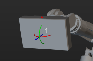
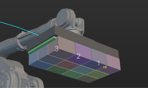
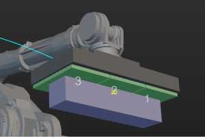
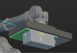
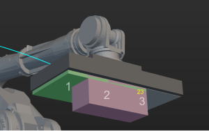
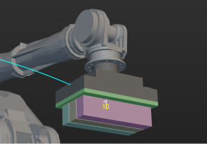
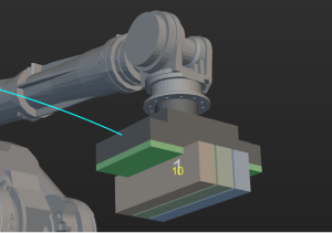
Improve the Depalletizing Algorithm in the “Vision Move” Step
In Mech-Viz 1.7.0, the depalletizing algorithm in the Vision Move Step has been restructured and improved, and the following picking methods are supported.
Single-section vacuum gripper |
|
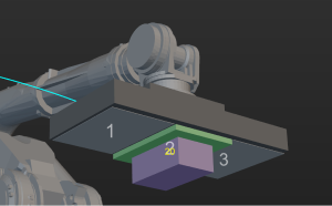
Multi-section vacuum gripper |
|
Pick a single object |
|
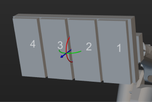
Pick multiple objects in a row |
|
Pick objects in multiple rows |
|
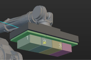
Center of the vacuum gripper coincides with that of the carton |
|
Midpoint of the vacuum gripper’s edge coincides with that of the carton’s edge |
|
Corner of the vacuum gripper coincides with that of the carton |
|
Long edges of objects are parallel to that of the vacuum gripper |
|
Long edges of objects are perpendicular to that of the vacuum gripper |
|
In addition, the software no longer restricts the X-axis of the TCP reference frame to be parallel to the long side of the vacuum gripper and the X-axis of the workpiece pick point reference frame to be parallel to the long side of the carton. There is no coupling between all the above features, and a variety of picking strategies can be configured by modifying the parameters.
Improved the Model Editor
A new “Set Frame” feature is added to the Model Editor. With this feature, you can set the origin and the directions of the axes for the reference frame. Therefore, the exported OBJ model can be accurately and quickly installed at the end of the robot flange.
The project in Model Editor is saved as M3D file and you do not need to create a folder to save the project.
OBJ models exported by Model Editor are compatible with Mech-Viz 1.6.0 and earlier.
Improved the Display Format of Euler Angles
The Euler angles are denoted differently on the teach pendant of different robot brands. For example, ABB uses EX, EY, and EZ; KUKA uses A, B, and C; while Kawasaki uses O, A, and T. In Mech-Viz 1.7.0, the display formats of Euler angles for some robot brands are integrated in the software. Once a robot is selected, the software will automatically switch the display format of Euler angles to the one corresponding to the selected robot, and the characters used by the robot brand will be displayed in the interface.
Improved Tool Configurations
In Mech-Viz 1.7.0, the tool configuration window is re-organized and improved. The new tool configuration window consists of the tool type options and “Configure control logic” button, and the symmetry configuration parameters have been improved.
Improved Workobject Configurations
The new workobject configuration window in Mech-Viz 1.7.0 aggregated functions related to workobject configurations that were in different locations in the software. The new workobject configuration window provides settings of the rotational symmetry, picking relaxation, and solution selection strategy.
Improved Scene Object Configurations
In Mech-Viz 1.7.0, the interfaces used for creating new scene objects and configuring scene objects are combined, and parameters for setting the effective range for poses have been improved.
Renamed Steps
Starting from Mech-Viz 1.7.0, “Skill” and “Task” have been renamed to “Step”. In addition, the names of the following Steps have been updated in Mech-Viz 1.7.0 for easier understanding of their functions. In addition, the format of all Step names have been changed to title-style capitalization.
Original Name |
New Name |
branch_by_guidepost |
Branch by Tag |
set_guidepost |
Set Tag for Branch |
move |
Fixed-Point Move |
update_picked_obj |
Update Held Workobject |
reset_task |
Reset |
tcp |
Change Tool |
set_pick_state |
Set Holding State |
payload |
Set Payload |
trajectory |
Path |
trajectory_procedure |
Path Procedure |
Others
Menu Bar
Removed the “Not Print Message Sent to Robot” option, and the messages sent to the robot will always be printed.
Removed the “Write Debug File (.dmp)” option. This feature is no longer supported.
Changed the default options of the global unit settings in from Use built-in units of Steps to mm and °.
Resources
Removed the “Autoload” button on the toolbar. You can go to the Resources panel, right-click the project name and select Autoload Project.
The interfaces used for suction cup configurations and tool configurations are combined, and the individual suction cup configuration file will not be saved.
When the tool configuration, workobject configuration, and scene objects configuration windows are opened, you can adjust the perspective and zoom in or out in the 3D simulation area at the same time.
Steps
Re-structured the layout of the buttons used for fast setting, pose transformation, pose calibration, and pose editing in move-type Steps.
The maximum port number in the “Set DO List” is increased to 30000.
The “unfinished” port of the “Check Look” Step is renamed to “Timeout”.
Improved the log when multi-pick depalletizing is used in the “Vision Move” Step. The carton combination information and carton offset planning details are included.
A new “Failure” exit port is added to the “Update Scene Objects” Step when vision service is used as the source for updating.
When the “Vision Move” Step is used to pick multiple cartons at one time, the model of the cartons to be picked together are displayed as multiple individual cartons instead of a single large carton.
Removed the “Selected” option from the Relative Move Dependency option in the “Relative Move” Step.
Removed the “set_robotiq” and “call_robot_function” Steps.
Removed the Save Successful Vision Result parameter and related features in the “Vision Move” Step.
Robot Functional Panel
Added value display for the dynamic limits of joint positions that changes as another joint position is adjusted.
For YASKAWA PL80, MPL80II, and MPL100II that have different display formats of the joint positions, the display format of joint positions in the interface is updated to match the joint positions displayed on the robot end.
The tool list will not be cleared after the robot is switched.
If the robot used in the project is lost, you can re-select other robot models in the robot library.
Collision Detection
Whether the collision detection between the point cloud and others is enabled or not, the point cloud of the held workobject will be removed by the “Vision Move” Step.
Whether the collision detection between the point cloud and others is enabled or not, the point cloud will be reset after resetting the “Vision Look” Step.
Software Communication
Added the “Skip waypoints approximate to others” parameter, which can be used to determine whether to send two waypoints that are close to each other.
Removed the “Send Tcp Pose” option in the Others functional panel, and the software will always send the TCP.
Resolved Issues
Mech-Viz 1.7.0 has fixed the following issues:
When an project built with earlier version software had not been opened successfully, part of the workflow was still loaded.
When a project was locked, a new user could be registered without the password.
Occasionally, users would not be prompted to save changes when closing the project.
When the project was simulating or running, the scene objects could be moved by dragging the axis of their reference frames.
When the project was simulating or running, the simulated robot could be moved by dragging the axis of the TCP reference frame.
The installation of the robot model might fail if there were uppercase letters in the name of the robot installation package.
When a new tool was created, the TCP reference frame in the 3D simulation area would not change with the new configuration.
When the workflow display was formatted, some Steps might overlap.
The search object might change after the search feature in the Workflow panel was enabled/disabled.
The error message in the “Vision Move” Step was incorrect when the vision service was not triggered by the “Vision Look” Step.
The error message was inaccurate when the “Vision Move” Step reused the vision result and failed to plan a path.
The error message was incorrect when the count of held workobjects reached the set value in the “Vision Move” Step.
In the “Update Held Workobject” Step, although the “Update Info Source” had been set to “Vision Service”, the object dimensions might still be updated from the parameters.
When the model type of the workobject was a custom model, the workobject model could not move with the real workobject.