Commands
This topic introduces the commands for Siemens PCL Snap 7 communication between a Siemens SIMATIC S7 PLC and Mech-Mind Software Suite.
Start Mech-Vision Project
This command starts the running of the Mech-Vision project, which executes image capturing, and performs vision recognition.
If the project works in the eye-in-hand mode, the robot pose for image capturing needs to be transmitted by this command into the project.
This command is for scenarios using only Mech-Vision.
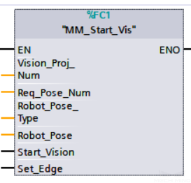
Parameters in command sent
Vision_Proj_Num
The integer ID number of the Mech-Vision project, displayed in the Project List panel in Mech-Vision. The ID number can be adjusted by dragging the projects.
Req_Pose_Num
The number of vision points (i.e., vision poses and their corresponding point clouds, labels, indices, etc.) to expect Mech-Vision to output.
0Get all the vision points from the Mech-Vision project’s recognition results.
integers > 0Get the specified number of vision points.
If the total number of vision points is smaller than the parameter value, all the available vision points will be returned.
If the total number of vision points is greater than or equal to the parameter value, vision points in the quantity of the parameter value will be returned.
Note
The command to obtain the vision points is Get Vision Target(s).
Robot_Pose_Type
This parameter indicates the type of pose of the real robot to input to Mech-Vision. The value range is 0–3.
Robot_Pose
This parameter is the robot pose sent to Mech-Vision. Its value depends on Robot_Pose_Type.
Data format: two-dimensional array [0..1, 0..5] of Real, array[0] is JPs and array[1] is flange pose.
The following table explains the relationship between Robot_Pose_Type and Robot_Pose.
Robot_Pose_Type value
Robot_Pose value
Description
Applicable scenario
0
0, 0, 0, 0, 0, 0
No need to input robot pose to Mech-Vision.
Project is in the eye-to-hand mode. If the “Path Planning” Step is used, the planned path starts at the Home point set in the path planning tool.
1
Current joint positions and flange pose of the robot
Robot joint positions and flange pose must be input to Mech-Vision as the image-capturing pose.
Project is in the eye-in-hand mode. Applicable to most robots (excluding truss robots).
2
Current flange pose of the robot
Robot flange pose must be input to Mech-Vision as the image-capturing pose.
Project is in the eye-in-hand mode. The robot has no joint positions and only flange pose (such as truss robots).
3
Joint positions of the start point of the planned path
The joint positions of the path start point must be input to Mech-Vision.
Project is in the eye-to-hand mode and the Mech-Vision project contains the “Path Planning” Step, whose start point needs to be set from the robot side.
Start_Vision
Trigger the start of the Mech-Vision project. The rising edge does the trigger.
Set_Edge
This parameter does not need to be set by the user.
It stores the value of “Start_Vision” in the last scan cycle to prevent unnecessary repetition of triggering.
Parameters in data returned
Status code
If there is no error, status code 1102 will be returned. Otherwise, the corresponding error code will be returned.
Example
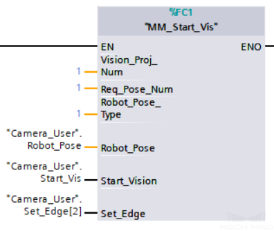
In this example, when the parameter “Camera_User”.Start_Vis has a rising edge, Mech-Vision project 1 will be triggered and will be expected to return the vision result, and PLC will send the robot JPs and flange pose to Mech-Vision when the Mech-Vision project is started.
Get Vision Target(s)
This command gets the vision result, i.e., vision points, after executing command 101.
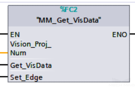
Parameters in command sent
Vision_Proj_Num
The integer ID number of the Mech-Vision project, displayed in the Project List panel in Mech-Vision. The ID number can be adjusted by dragging the projects.
Get_VisData
The signal to request the result from the Mech-Vision project. The rising edge does the trigger.
Set_Edge
This parameter does not need to be set by the user.
It stores the value of “Get_VisData” in the last scan cycle to prevent unnecessary repetition of triggering.
Parameters in data returned
Status code
If there is no error, status code 1100 will be returned. Otherwise, the corresponding error code will be returned.
Status of Pose Sent
1means the pose data written is new.After PLC reads the pose data, please reset this register;
Number of Pose Sent
The number of poses transmitted by executing the command “Get Vision Target(s)” this time.
Range: [1, 40].
Note
For Siemens PLC, by default, the upper limit of the number of poses transmitted by calling this command each time is 40. So, this command may need to be executed multiple times before all the poses in the vision result are returned.
Target Pose
The robot waypoint poses (as TCPs) converted from the vision poses of the Mech-Vision project.
Target Label
The labels reflecting object info corresponding to the vision targets. The labels are integers.
Example
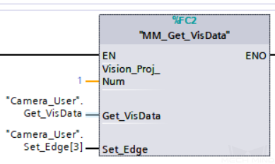
In this example, when the parameter “Camera_User”.Get_VisData has a rising edge, it is used to get the vision result of Mech-Vision project 1.
Switch Mech-Vision Recipe
This command switches the parameter recipe used by the Mech-Vision project.
In Mech-Vision, you can change the settings of a group of parameters by switching the parameter recipe.
Parameters involved in recipe switching usually include point cloud matching model, image matching template, ROI, confidence threshold, etc.
This command needs to be used before executing command 101 which starts the Mech-Vision project.
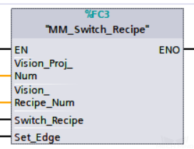
Parameters in command sent
Vision_Proj_Num
The integer ID number of the Mech-Vision project, displayed in the Project List panel in Mech-Vision. The ID number can be adjusted by dragging the projects.
Vision_Recipe_Num
The ID number of the parameter recipe to switch to, i.e., the number on the left of the parameter recipe name in in Mech-Vision.
Switch_Recipe
The trigger signal to switch the recipe. The rising edge does the trigger.
Set_Edge
This parameter does not need to be set by the user.
It stores the value of “Switch_Recipe” in the last scan cycle to prevent unnecessary repetition of triggering.
Parameters in data returned
Status code
If there is no error, status code 1107 will be returned. Otherwise, the corresponding error code will be returned.
Example
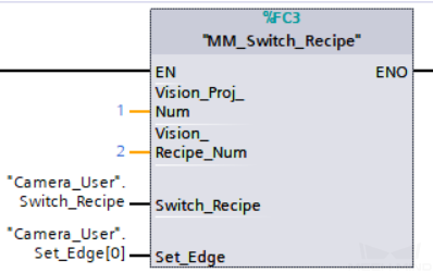
In this example, when the variable “Camera_User”.Switch_Recipe has a rising edge, it will switch the recipe of Mech-Vision project 1 to recipe 2.
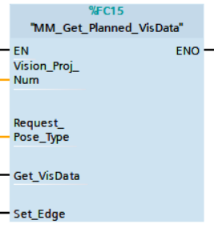
Get Result of Step “Path Planning” in Mech-Vision
This command gets the collision-free path planning result of the “Path Planning” Step in Mech-Vision, after executing command 101.
When using this command, the Port Type parameter of the “Procedure Out” Step must be set to Predefined (robot path).
Hint
Before executing this command, please set Req_Pose_Num in MM_Start_Vis to 0 to reduce the times of execution of this command. If Req_Pose_Num in MM_Start_Vis is set to 1, then every time this command is executed, only 1 waypoint is returned, and this command must be executed multiple times to obtain all the waypoints.
Parameters in command sent
Vision_Proj_Num
The integer ID number of the Mech-Vision project, displayed in the Project List panel in Mech-Vision. The ID number can be adjusted by dragging the projects.
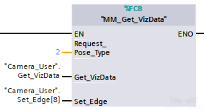
Request_Pose_Type
The type of waypoint pose returned by the “Path Planning” Step.
1: The waypoint poses are returned in the form of JPs.
2: The waypoint poses are returned in the form of TCP.Attention
Request_Pose_Type and Robot_Pose_Type in the MM_Start_Vis and MM_Start_Viz functions correspond to the same Pose Type parameter in the Mech-Mind Interface data block. If the set values are different, they cannot take effect at the same time.
Get_VisData
The signal to request the result from the Mech-Vision project. The rising edge does the trigger.
Set_Edge
This parameter does not need to be set by the user.
It stores the value of “Get_VisData” in the last scan cycle to prevent unnecessary repetition of triggering.
Parameters in data returned
Status code
If there is no error, status code 1103 will be returned. Otherwise, the corresponding error code will be returned.
Status of Pose Sent
1 means that the written pose data is new data. After PLC reads the pose data, please reset this register;
Number of Pose Sent
This parameter indicates the number of path waypoints ([pose, label, velocity]) sent by executing this command this time.
Default range: 1 to 20.
Index of Vision Move
The position of the Vision Move Step, i.e., the move to the vision pose (usually the pose for picking the object) in the entire robot motion path.
For example, if the path is composed of Steps Move_1, Move_2, Vision Move, Move_3 sequentially, the position of Vision Move is 3.
If in the path there is no Vision Move Step, the returned value will be 0.
Target Pose
The poses of the waypoints in the planned path.
Each pose includes Cartesian coordinates (XYZ) and Euler angles (ABC), or JPS, according to the value of Request_Pose_Type of this command.
Target Label
The labels of the waypoints in the planned path.
A label is the integer label assigned to a pose. If in the Mech-Vision project, the labels are strings, they need to be mapped to integers before outputting from the Mech-Vision project using Step Label Mapping. If there are no labels in the Mech-Vision project, the label defaults to 0.
Speed Percentage
The velocities of the waypoints set in the path planning tool of Mech-Vision.
Example
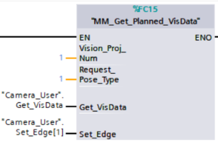
In this example, when the variable “Camera_User”.Get_VisData has a rising edge, it is used to receive the robot path planned by Mech-Vision project 1, and the waypoint poses in the path are in the form of JPs.
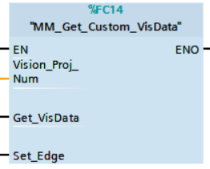
Get Custom Output Data from Mech-Vision
This command is for receiving custom data, i.e., data other than poses and labels, from Step “Procedure Out” in Mech-Vision (when the parameter “Port Type” is set to “Custom”).
This command is for scenarios using only Mech-Vision.
Parameters in command sent
Vision_Proj_Num
The integer ID number of the Mech-Vision project, displayed in the Project List panel in Mech-Vision. The ID number can be adjusted by dragging the projects.
Get_VisData
The signal to request the result from the Mech-Vision project. The rising edge does the trigger.
Set_Edge
This parameter does not need to be set by the user.
It stores the value of “Get_VisData” in the last scan cycle to prevent unnecessary repetition of triggering.
Parameters in data returned
Status code
If there is no error, status code 1100 will be returned. Otherwise, the corresponding error code will be returned.
Status of Pose Sent
1 means that the written pose data is new data. After PLC reads the pose data, please reset this register;
Number of Pose Sent
This parameter indicates the number of path waypoints ([pose, label, velocity]) sent by executing this command this time.
Default range: 1 to 20.
Target Pose
The poses (as TCPs) returned by Mech-Vision.
Target Label
The labels of the waypoints in the planned path.
A label is the integer label assigned to a pose. If in the Mech-Vision project, the labels are strings, they need to be mapped to integers before outputting from the Mech-Vision project using Step Label Mapping. If there are no labels in the Mech-Vision project, the label defaults to 0.
Custom Data Output
The custom data for the corresponding port of custom data type on Step “Procedure Out”.
The custom data parameters are arranged in alphabetical order A–Z by port name.
Example
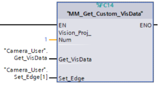
In this example, when the variable “Camera_User”.Get_VisData has a rising edge, it is used to receive the vision result that includes custom data by Mech-Vision project 1.
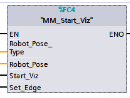
Start Mech-Viz Project
This command is for scenarios using both Mech-Vision and Mech-Viz.
This command starts the running of the Mech-Viz project, calls the corresponding Mech-Vision project, and lets the Mech-Viz project plan the robot path based on the vision points from Mech-Vision.
Please see Example Mech-Viz Projects for Standard Interface for the description of example Mech-Viz projects.
Parameters in command sent
Robot_Pose_Type
This parameter indicates the type of the robot pose of the real robot to input to Mech-Viz. The value range is 0–2.
Robot_Pose
This parameter is the robot pose sent to Mech-Viz. Its value depends on Robot_Pose_Type.
Data format: two-dimensional array [0..1, 0..5] of Real, array[0] is JPs and array[1] is flange pose.
The following table explains the relationship between Robot_Pose_Type and Robot_Pose.
Robot_Pose_Type value
Robot_Pose value
Description
Applicable scenario
0
0, 0, 0, 0, 0, 0
No need to input robot pose to Mech-Viz. The simulated robot in Mech-Viz moves from joint positions = [0, 0, 0, 0, 0, 0] to the first waypoint.
Project is in the eye-to-hand mode. This setting is not recommended.
1
Current joint positions and flange pose of the robot
Robot joint positions and flange pose must be input to Mech-Viz. The simulated robot in Mech-Viz moves from the input joint positions to the first waypoint.
This setting is recommended for projects in the eye-in-hand mode.
2
Specific joint positions of the robot
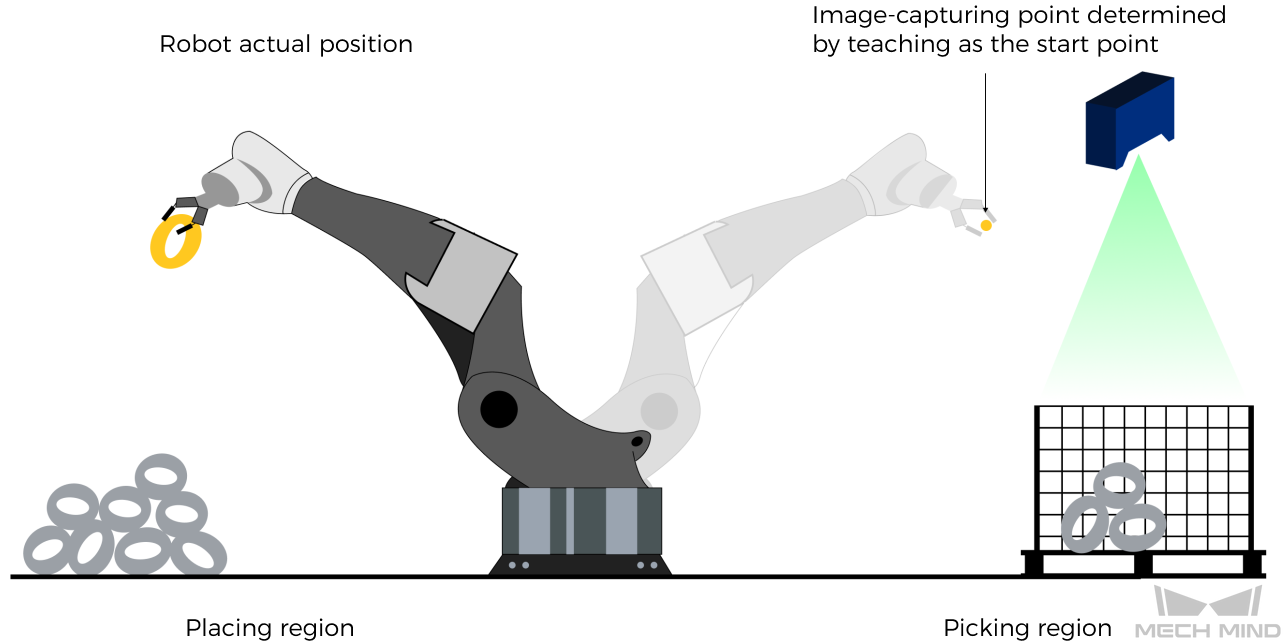
The robot joint positions of a point determined by teaching must be input to Mech-Viz. The input joint positions are used to trigger Mech-Viz to plan the next path in advance while the robot is not in the camera capture region, as shown below. The simulated robot in Mech-Viz moves from the input joint positions to the first waypoint.
This setting is recommended for projects in the eye-to-hand mode.
The reason for setting Robot_Pose_Type to 2 when the project is in the eye-to-hand mode:
In the eye-to-hand mode, the camera can perform image capturing for the next round of path planning before the robot returns to the camera capture region and picking region, shortening the cycle time.
If Robot_Pose_Type is set to 1, the robot’s current pose is sent to Mech-Viz. The simulated robot will move from the input pose to the first waypoint in the planned path, while the real robot might move to another point first, and then move to the first waypoint. Therefore, the path of the real robot may contain unpredicted collisions, leading to safety hazards.
In conclusion, Robot_Pose_Type should be set to 2 for projects in the eye-to-hand mode.
Start_Viz
The signal to trigger the running of the Mech-Viz project. The rising edge does the trigger.
Set_Edge
This parameter does not need to be set by the user.
It stores the value of “Start_Viz” in the last scan cycle to prevent unnecessary repetition of triggering.
Parameters in data returned
Status code
If there is no error, status code 2103 will be returned. Otherwise, the corresponding error code will be returned.
Example
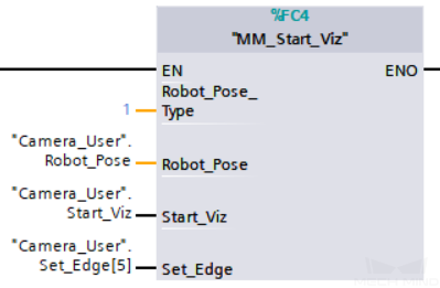
In this example, when the variable “Camera_User”.Start_Viz has a rising edge, the Mech-Viz project will be triggered to run, and the current JPs and flange pose of the robot will be sent to Mech-Viz.
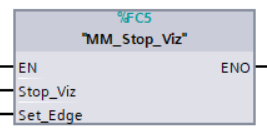
Stop Mech-Viz Project
This command stops the running of the Mech-Viz project. This command is needed only when the Mech-Viz project falls into an infinite loop or cannot be stopped normally.
Parameters in command sent
Stop_Viz
The trigger signal to stop the running of the Mech-Viz project, the rising edge is valid;
Set_Edge
This parameter does not need to be set by the user.
It stores the value of “Stop_Viz” in the last scan cycle to prevent unnecessary repetition of triggering.
Parameters in data returned
Status code
If there is no error, status code 2104 will be returned. Otherwise, the corresponding error code will be returned.
Example
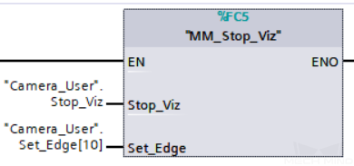
In this example, the Mech-Viz project is stopped when a rising edge occurs on the variable “Camera_User”.Stop_Viz.
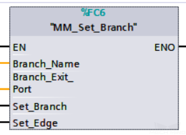
Select Mech-Viz Branch
This command specifies which branch the project should run along. For this command, the branching is implemented by a “Branch by Msg” Step, and this command selects the branch by specifying an exit port of the Step.
Before executing this command, the Mech-Viz project needs to be started by executing command 201.
When the Mech-Viz project runs to the “Branch by Msg” Step, it will wait for command 203 to specify which exit port of the Step, i.e., the branch, the project should run along.
Parameters in command sent
Branch_Name
The Step ID of the Branch by Msg Step.
This parameter is for specifying which Branch by Msg Step the branch selection should apply to.
The Step ID can be read in the Step’s parameters.
Branch_Exit_Port
This parameter is for specifying which exit port of the specified Step, i.e., the branch, the project should run along. The value should be an integer ([1, N]).
Note
An exit port number is the 1-based index of the specified exit port on the Step. For example, if the specified exit port is the second exit port of the Step from left to right, the exit port number is 2.
Set_Branch
The trigger signal for setting the branch. The rising edge does the trigger.
Set_Edge
This parameter does not need to be set by the user.
It stores the value of “Set_Branch” in the last scan cycle to prevent unnecessary repetition of triggering.
Parameters in data returned
Status code
If there is no error, status code 2105 will be returned. Otherwise, the corresponding error code will be returned.
Example
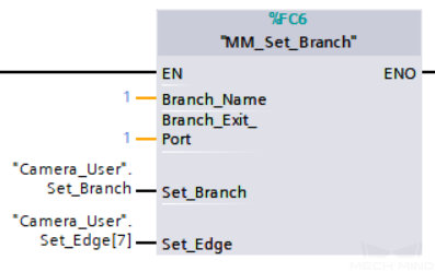
In this example, when the variable “Camera_User”.Set_Branch has a rising edge, it will specify that the project should run along the 1st outport of the Step whose Step ID is 1 when executing the Step.
Set Move Index
This command is for setting the index parameter of a Step that involves sequential or separate motions or operations.
Steps with index parameters include Move by List, Move by Grid, Custom Pallet Pattern, Smart Pallet Pattern, etc.
Before executing this command, command 201 needs to be executed to start the Mech-Viz project.
Parameters in command sent
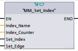
Index_Name
The Step ID of the Branch by Msg Step.
This parameter specifies which Step the index setting should apply to.
The Step ID can be read in the Step’s parameters.
Index_Counter:
The index value that should be set the next time this Step is executed.
When this command is sent, the current index value in Mech-Viz will become the parameter value minus 1.
When the Mech-Viz project runs to the Step specified by this command, the current index value in Mech-Viz will be increased by 1 to become the parameter’s value.
Set_Index
The trigger signal to set the index. The rising edge does the trigger.
Set_Edge
This parameter does not need to be set by the user.
It stores the value of “Set_Index” in the last scan cycle to prevent unnecessary repetition of triggering.
Parameters in data returned
Status code
If there is no error, status code 2106 will be returned. Otherwise, the corresponding error code will be returned.
Example
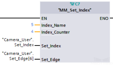
In this example, when the parameter “Camera_User”.Set_Index has a rising edge, in the Mech-Viz project, the index of the Step whose Step ID is 5 will be set to “4”. Later, when the project runs to this Step, the index value will be incremented by 1 to be “5” .
Get Planned Path
This command gets the robot motion path planned by Mech-Viz after command 201 is executed to start the Mech-Viz project.
Note
If one of the waypoints in the path is not supposed to be sent to the robot, please clear the parameter “Send Waypoint” checkbox of the corresponding move-type Step.
Parameters in command sent
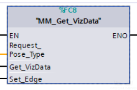
Request_Pose_Type
This parameter specifies the type of waypoint poses to return from Mech-Viz.
1: The waypoint poses returned should be in JPs.
2: The waypoint poses returned should be in TCP.Get_VizData
The trigger signal to obtain the planned path from Mech-Viz. The rising edge does the trigger.
Set_Edge
This parameter does not need to be set by the user.
It stores the value of “Get_VizData” in the last scan cycle to prevent unnecessary repetition of triggering.
Parameters in data returned
Status code
If there is no error, status code 2100 will be returned. Otherwise, the corresponding error code will be returned.
Note
When executing this command, if Mech-Viz has not yet had the planned robot motion path (the project is still running), this command will wait before sending the results to the robot. The default wait time is 10 seconds. If a timeout occurs, the timeout error status code will be returned.
Status of Pose Sent
1 means that the written pose data is new data. After PLC reads the pose data, please reset this register;
Number of Pose Sent
This parameter indicates the number of path waypoints ([pose, label, velocity]) sent by executing this command this time.
Default range: 1 to 20.
Note
In Siemens PLC, by default, executing command 205 once can fetch at most 20 waypoints (poses, labels, velocities) at a time. If the number of waypoints is greater than 20, please execute command 205 multiple times.
Index of Vision Move
The position of the Vision Move Step, i.e., the move to the vision pose (usually the pose for picking the object) in the entire robot motion path.
For example, if the path is composed of Steps Move_1, Move_2, Vision Move, Move_3 sequentially, the position of Vision Move is 3.
If in the path there is no Vision Move Step, the returned value will be 0.
Target Pose
The poses of the waypoints in the planned path.
Each pose includes Cartesian coordinates (XYZ) and Euler angles (ABC), or JPS, according to the value of Request_Pose_Type of this command.
Target Label
The labels of the waypoints in the planned path.
A label is the integer label assigned to a pose. If in the Mech-Vision project, the labels are strings, they need to be mapped to integers before outputting from the Mech-Vision project using Step Label Mapping. If there are no labels in the Mech-Vision project, the label defaults to 0.
Speed Percentage
The velocities of the waypoints in the planned path.
A velocity is the non-zero velocity parameter percentage value for the corresponding move-type Step in Mech-Viz.
Example
In this example, when the variable “Camera_User”.Get_VizData has a rising edge, it is used to receive the robot movement path planned by Mech-Viz, and the waypoints in the path are in the form of TCP.
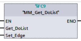
Get DO List
This command gets the planned DO signal list when there are multiple grippers, such as suction cup sections, to control.
The command “Get Planned Path” needs to be executed before executing this command.
For using this command:
In the parameters of the Set DO List Step:
Select “Standard Interface” under “Receiver”
Select “Get DO List from ‘Vision Move’”
Select a Vision Move Step that needs the DO signal list in the drop-down list of the “Select ‘Vision Move’” parameter
Hint
Please refer to the Mech-Viz template project in xxx\Mech-Mind Software Suite-x.x.x\Mech-Center\tool\viz_project\suction_zone, and set the corresponding suction cup configuration file in the project before running.
Parameters in command sent
Get_DoList
Trigger signal for obtaining the DO signal list. The rising edge does the trigger.
Set_Edge
This parameter does not need to be set by the user.
It stores the value of “Get_DoList” in the last scan cycle to prevent unnecessary repetition of triggering.
Parameters in data returned
Status code
If there is no error, 2102 will be returned. Otherwise, the corresponding error code will be returned.
DO
The sixty-four DO signal values returned by executing this command. A valid DO value is in the range of [0, 999], and -1 is a placeholder value.
Example
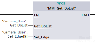
In this example, when the parameter “Camera_User”.Get_DoList has a rising edge, the DO values from Mech-Viz will be stored in the DO list.
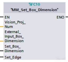
Input Object Dimensions to Mech-Vision
This command is for dynamically inputting object dimensions to the Mech-Vision project, and has to be executed before executing MM_Start_Vis. The corresponding Mech-Vision project must contain the “Read Object Dimensions” Step, and the Read Sizes from Properties parameter of this step must be checked.
Parameters in command sent
Vision_Proj_Num
The integer ID number of the Mech-Vision project, displayed in the Project List panel in Mech-Vision. The ID number can be adjusted by dragging the projects.
External_Input_Box_Dimension
The 3D dimensions to input to the Mech-Vision project.
Unit: mm
Data type: Array[0–2] of Real
Set_Box_Dimension:
The trigger signal to input the dimensions. The rising edge does the trigger.
Set_Edge
This parameter does not need to be set by the user.
It stores the value of “Set_Box_Dimension” in the last scan cycle to prevent unnecessary repetition of triggering.
Parameters in data returned
Status code
If there is no error, 1108 will be returned. Otherwise, the corresponding error code will be returned.
Example
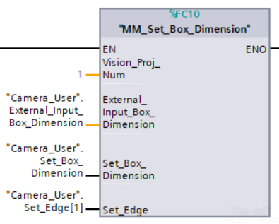
In this example, when the parameter “Camera_User”.Set_Box_Dimension has a rising edge, the dimensions read by Step “Read Object Dimensions” will be set to the value of External_Input_Box_Dimension.
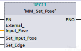
Input TCP to Mech-Viz
This command is for dynamically inputting robot TCP data to Mech-Viz to work with Step “external_move” in Mech-Viz.
Hint
Please deploy the Mech-Viz project based on the template project at xxx\Mech-Mind Software Suite-x.x.x\Mech-Center\tool\viz_project\outer_move, and put the External Move Step to a proper position in the workflow.
Parameters in command sent
External_Input_Pose
The parameter stores the TCP data to be sent to Mech-Viz.
Data type: Array[0–5] of Real
Set_Input_Pose
The trigger signal for inputting the TCP data. The rising edge does the trigger.
Set_Edge
This parameter does not need to be set by the user.
It stores the value of “Set_Input_Pose” in the last scan cycle to prevent unnecessary repetition of triggering.
Parameters in data returned
Status code
If there is no error, 2107 will be returned. Otherwise, the corresponding error code will be returned.
Example
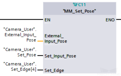
In this example, when the parameter “Camera_User”.Set_Input_Pose has a rising edge, the data in External_Input_Pose will be sent to Step “outer_move” in Mech-Viz.
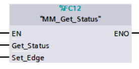
Get Software Status
This command is for obtaining the running status of Mech-Vision, Mech-Viz, Mech-Center (at present, only whether Mech-Vision is ready to start running the project can be checked).
Parameters in command sent
Get_Status
The trigger signal for checking whether Mech-Vision is ready to start running the project. The rising edge does the trigger.
Set_Edge
This parameter does not need to be set by the user.
It stores the value of “Get_Status” in the last scan cycle to prevent unnecessary repetition of triggering.
Parameters in data returned
Status code
Software status. 1101 means the Mech-Vision project is ready to run. Other codes mean the project is not ready.
Example
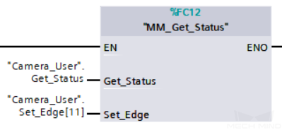
In this example, when the parameter “Camera_User”.Get_Status has a rising edge. The software running status will be checked and the result will be stored in the parameter “Status code”.
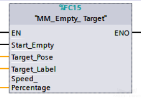
Clear Waypoint Data
This command is for clearing the acquired data in Target Pose, Target Label, Speed Percentage.
Parameters in command sent
Start_Empty
The trigger signal to clear the obtained data in Target Pose, Target Label, Speed Percentage. The signal takes effect when it is set high.
Target_Pose
This parameter stores the obtained waypoint pose data.
Target_Label
This parameter stores the obtained waypoint labels.
Speed_Percentage
This parameter stores the obtained non-zero speed parameters of waypoints.
Example
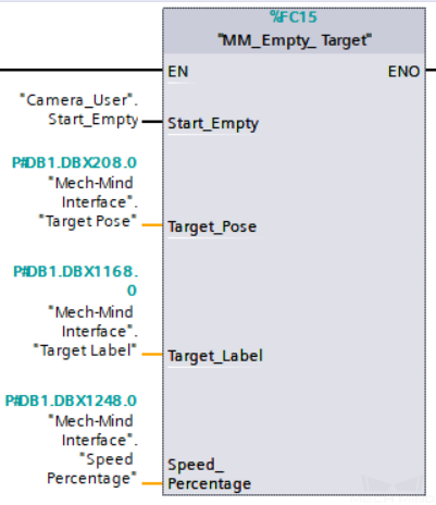
In this example, when the parameter “Camera_User”.Start_Empty is set to 1, the acquired data in Target Pose, Target Label, Speed Percentage will be cleared.