Custom Pallet Pattern
Note
Contents of this Step are under maintenance. If you need more information about this Step with urgency, please contact us at docs@mech-mind.net.
Function
Using Custom Pallet Pattern Step, you can manually draw a pallet pattern that meets special needs and peform palletizing.
Parameter Description
Move-Type Step Common Parameters
Please refer to General Parameters of Move-Type Steps for detailed information.
Held Workobject Collision Detection Settings
Please refer to Held Workobject Collision Detection Settings for detailed information.
Index
- Start Index
Description: specifies the index of the box to place.
Value: an integer. The default value is 0.
Instruction: When the pallet is empty, set this parameter to 0 . If the palletizing is interrupted and then the palletizing process continues, set this parameter to N when N boxes have been palletized. In this case, the program will continue to pallet the N+1th box.
- Current Index
Description: the index of the box to display. If it is set to N, the N+1th box will be displayed.
Value: is an integer and automatically read. When an external command is received, it will be updated accordingly.
Basic Pallet Setting
- Hide Trajectory
: default value. It displays the trajectory of the box getting into the pallet.
: hides the trajectory of the box getting into the pallet.
- Moves Count
Displays the number of objects that can be placed on the tray and its value is not editable.
Motion Control
- Auto Middle Point Force Move J
- Entry/Adjust/Place Force Move J
- Acc&Vel Scale Ratio
Value: 0–100%; the default value is 100%.
Usage scenarios: this parameter is used when the velocities of the robot approaching the pallet and placing the boxes are different.
Description: The actual acceleration & velocity of the robot placing the box is the product of Acceleration & Velocity multiplied by Acc&Vel Scale Ratio .
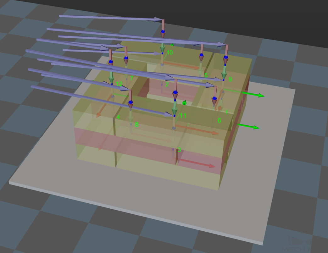
Entry to the pallet is divided into three phases of move:
Phase 1: purple (approach the pallet)Phase 2: pink (place the box)Phase 3: green (place the box)The acceleration and velocity of approaching the pallet are specified in Basic Move Settings, while those of the last two phases are the product of Acceleration & Velocity multiplied by Acc&Vel Scale Ratio .
Entry Adjust
Instruction: The three parameters of this group together control the path of the box’s entry to the pallet. You are suggested to adjust the path to make the box to pallet approach the palleted boxes at a certain angle and put down the box vertically. This prevents the box to pallet from colliding with the palleted boxes due to accuracy or other reasons when the robot directly puts down the box vertically.
For each box, there are four positions for its entry to the pallet. This group of parameters controls three of them, that is, entry, adjust, and place positions, which are shown as the red points in the following figure. The following figure provides a main view of the placed boxes.
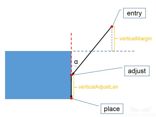
- Vertical Adjust Length Ratio
Description: it affects the adjust position (adjust point in the preceding figure).
Parameter = verticalAdjustLen / Box height
Value range: 0–1
Recommended value: 0.5
- Vertical Margin
Description: determines the entry position (entry point in the preceding figure).
Parameter = Height margin
Value range: 0 – ∞, in mm. It should be set according to actual requirements to leave enough margin.
- Entry Angle Z
Description: determines the angle (α in the preceding figure) between the path from the entry position (entry point in the preceding figure) to the adjust position (adjust point in the preceding figure) and the vertical direction, in °.
Value range: -80°–80°
Recommended value: 30°–45°
Auto Middle Point
- X/Y
Set the position (x, y) of the pink ball in the robot base frame x, y. Based on this position, reasonable middle points will automatically be calculated for the pallets of different heights.
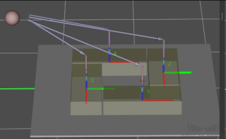
- Min Z
Specified the minimum absolute z-directional height (the difference between the z-directional height and the height of this layer) at the time of robot entry (purple path), as shown in the following figure.

- Is Middle Point Traj Vertical
- Extended Distance for Entry
Usage scenarios: It is used in scenarios where the gripper is big and the length of the entry path is not long enough to ensure that the gripper does not collide with the palletized pattern. You can set this parameter to ensure operation safty.
Attention
Auto Middle Point functions only as a direction indicator for pallet entry, rather than the point that the real robot must reach. Therefore, the pink ball should be as far away from the tray as possible. If the ball is too close to the pallet, extrusion and collision may occur when the boxes are being placed.
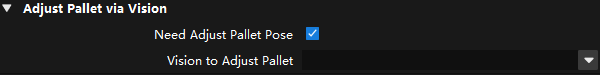
Adjust Pallet via Vision
Description: dynamically adjusts the position of the pallet by Vision Look .
- Need Adjust Pallet Pose
- Vision to Adjust Pallet
Specifies the Mech-Vision project used to recognize the position of the pallet ( Vision Look ). When this Step is executed, the Vision Look Step will be called based on the Mech-Vision project name.
Hint
The position of the pallet can also be adjusted by external settings (adapter).
For Depalletization
- As Vision Service
Once this parameter is checked, the corresponding step can provide vision service for Vision Look instead of Mech-Vision.
- Dynamic Load
“Dynamic Load” is achieved by dynamically setting the pallet configuration file through a function in the “Adapter”.
- Auto Entry Angle
After checking this parameter, the entry angle will be adjusted automatically without setting the parameter.
Basic Move
- Motion type
- J: Joint motion, which guides the robot to move in a curved path. It is less likely to reach singularities in the path for joint motion. This motion type is applicable to scenarios where the requirement of path accuracy is not strict and the robot moves in a large space.L: Linear motion, which guides the robot to move linearly. This motion type is applicable to scenarios where there is a strict requirement of the path accuracy, such as welding, gluing, and certain types of picking.
- Acceleration & Vel Velocity
- Default setting: The default acceleration is set to 50%, and the default velocity is set to 100%.Instruction: The acceleration and velocity specify the cycle time of the robot. The acceleration value is usually set below the velocity, or else the robot may not move steadily.
Attention
The velocities of Vision Move and its prior and subsequent Steps should be relatively low to make sure that the objects can be picked steadily.
- Blend radius
- Default setting: 50.00mmDefinition: The blend radius refers to the distance between the target point and the point where the robot starts to turn. The larger the blend radius, the more smoother the robot motion transitions are.Instruction: Usually, the default setting can be used. If the robot moves in a relatively small space, please set the blend radius to a smaller value. If the robot moves in a relatively large space without obstacles and the distance between two consecutive path segments are long, please set the blend radius to a larger value.
- Pick or place
- Default setting: Unspecified
Pallet
You can adjust the pose of the pallet by setting the parameters of Euler angles or Quaternion .
Pallet Editor
Click Pallet Editor to pop up the interface of the Pallet Editor .
Please refer to Pallet Editor for detailed information of the Pallet Editor .
load Pattern
Click Load Pattern to select the pallet configuration file in JSON format.