Siemens PLC Client - SIMATIC STEP 7
This topic provides instructions on setting up the Standard Interface communication based on the Siemens PLC Snap7 protocol between a Siemens SIMATIC S7 PLC and Mech-Mind Software Suite using the SIMATIC Manager STEP7 software.
Software and Hardware Prerequisites
Hardware
The following S7 series PLCs from Siemens are supported:
S7-300: Integrated PN network port or CP343-1
S7-400: Integrated PN network port or CP443-1
Power adapter of 220V AC to 24V DC
IPC or host for Mech-Mind Vision System
Network cable
Software
Siemens PLC programming software SIMATIC Manager Step7 V5.6.
Mech-Mind Software Suite: 1.7.0 or above.
Communication interface file between Vision system and S7: MM_Interface_Step7.AWL.
Hint
MM_Interface_Step7.AWL file is located in xxx\Mech-Mind Software Suite-x.x.x\Mech-Center\Robot_Interface\Siemens Snap7\Simatic Manager-STEP7 in the installation directory of Mech-Mind Software Suite.
PLC Project Building and Deployment
Create a PLC Project
Open the software SIMATIC Manager, click the button
 in the upper left corner, enter the project name and storage path in the pop-up window.
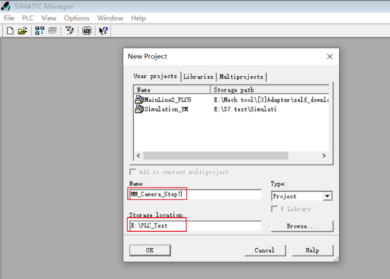
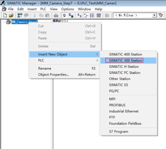
Right-click MM_Camera_Step7 , select . After inserting, right-click and select Open Project to enter the hardware configuration interface.
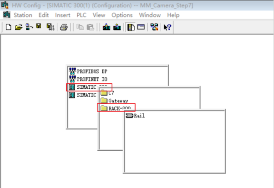
In the blank space of the hardware configuration interface, click the right mouse button and select to insert the mounting rail.
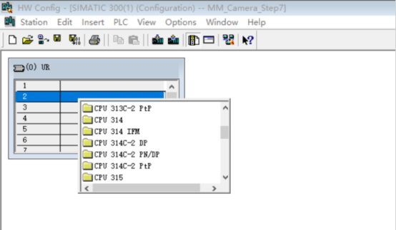
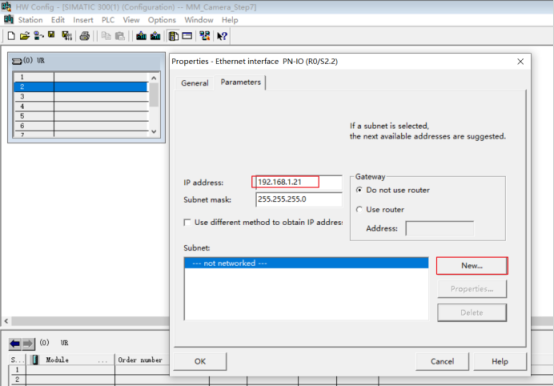
In the second row slot of the mounting rail, right-click, select Insert Object, select the module that is consistent with the PLC CPU (the module has to support the PN network port), and the Ethernet Interface Property window will pop up.
After setting the IP address, click New Subnet (the subnet name can be set as the default name), then select the newly created subnet, and click OK .
After clicking
 Compile and Save on the title bar, close the Hardware Configuration window.
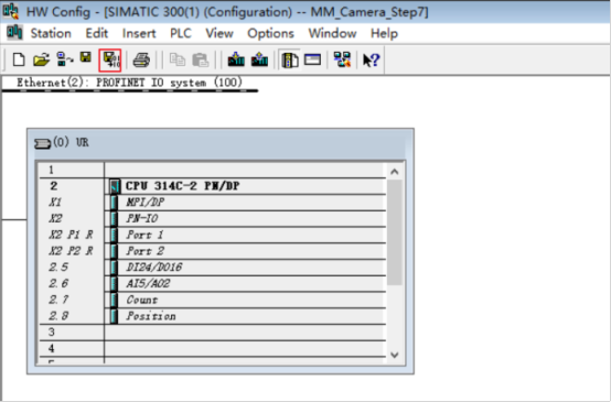
Import the S7 Communication Interface
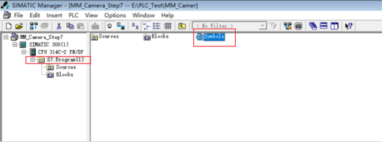
Return to the SIMATIC Manager main interface, select S7 Program, right-click, open the Symbols table, add a new symbol Mech-Mind Interface, and select an unoccupied number for the DB number in the address column.
After adding the new symbol, as shown in the figure below, click the button
 Save after confirming the settings are correct.
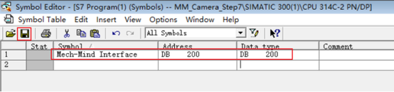
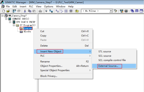
Right-click Sources in the project section on the left, select in turn, select MM_Interface_Step7.AWL in the pop-up window and open it.
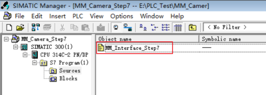
After importing the file, it will look like this:
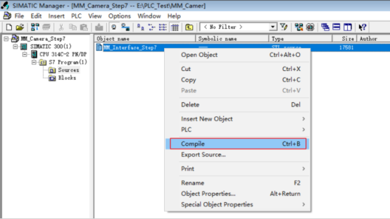
Right-click and select MM_Interface_Step7 , select Compile , and close the window after the compilation is successful.
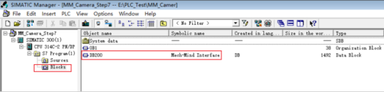
Select Blocks , right-click and select Details , and you can find that Mech-Mind Interface has been imported successfully.
Right-click SIMATIC 300 in the project section on the left. Click the button
 Download on the tool bar to download the project to the CPU.
Configure and Start Communication
Click Robot and Interface Configuration on the toolbar of Mech-Vision.
Select Listed robot from the Select robot drop-down menu, and then click Select robot model.
Select the robot model that you use, and then click Next.
Select the following options and click Apply.
Interface Type: Standard Interface
Protocol: Siemens PLC Client
PLC IP address: according to the setting in SIMATIC Manager
Slot number: 2
DB number: 200
Make sure the Interface Service is started: on the toolbar of Mech-Vision, the Interface Service switch on the far right is flipped and turned to blue.
The PLC is successfully connected if the following message is displayed in the Console tab of Mech-Vision Log panel:
Connect to PLC server successfully
If not, please check the configuration and check whether the physical connection is normal.
Start the deployed Mech-Vision and Mech-Viz projects.
Hint
For the specific usage of DB and interface communication instructions, please refer to Siemens PLC and Commands .