Siemens PLC
This topic introduces the Standard Interface commands according to the Siemens PLC Snap7 protocol.
The commands are as follows:
Command 101: Start Mech-Vision Project
This command starts the running of the Mech-Vision project, which executes image capturing, and performs vision recognition.
If the project works in the eye-in-hand mode, the robot pose for image capturing needs to be transmitted by this command into the project.
This command is for scenarios using only Mech-Vision.
Command Sent
Parameter |
DB offset |
|---|---|
Command code 101 |
2.0 |
Project number |
8.0 |
Expected number of vision points |
6.0 |
Robot pose type |
4.0 |
Robot pose |
12.0 (JPs) or 36.0 (flange pose) |
Project number
The integer ID number of the Mech-Vision project, displayed in the Project List panel in Mech-Vision. The ID number can be adjusted by dragging the projects.
Expected number of vision points
The number of vision points (i.e., vision poses and their corresponding point clouds, labels, indices, etc.) to expect Mech-Vision to output.
0Get all the vision points from the Mech-Vision project’s recognition results.
integers > 0Get the specified number of vision points.
If the total number of vision points is smaller than the parameter value, all the available vision points will be returned.
If the total number of vision points is greater than or equal to the parameter value, vision points in the quantity of the parameter value will be returned.
Note
The command to obtain the vision points is command 102.
Robot pose type and robot pose
Robot pose type indicates the type of pose of the real robot to input to Mech-Vision. The value range is 0–3.
The value of robot pose depends on the value of robot pose type.
The following table explains the relationship between the two parameters.
Robot pose type value
Robot pose value
Description
Applicable scenario
0
0, 0, 0, 0, 0, 0
No need to input robot pose to Mech-Vision.
Project is in the eye-to-hand mode. If the “Path Planning” Step is used, the planned path starts at the Home point set in the path planning tool.
1
Current JPs and flange pose of the robot
Robot JPs and flange pose must be input to Mech-Vision as the image-capturing pose.
Project is in the eye-in-hand mode. Applicable to most robots (excluding truss robots).
2
Current flange pose of the robot
Robot flange pose must be input to Mech-Vision as the image-capturing pose.
Project is in the eye-in-hand mode. The robot has no JPs and only flange pose (such as truss robots).
3
JPs of the start point of the planned path
The JPs of the path start point must be input to Mech-Vision.
Project is in the eye-to-hand mode and the Mech-Vision project contains the “Path Planning” Step, whose start point needs to be set from the robot side.
The data format of the robot pose is Real.
Data Returned
Parameter |
DB offset |
|---|---|
Status code |
200.0 |
Status code
If there is no error, status code 1102 will be returned. Otherwise, the corresponding error code will be returned.
Command 102: Get Vision Target(s)
This command is called after Command 101: Start Mech-Vision Project to obtain the vision points output by Mech-Vision and transform the vision points to vision targets.
The transformation process is as follows:
Rotate the poses around their Y axes by 180 degrees.
Determine whether the definition of the reference frame used by the robot model involves robot base height, and add a vertical offset accordingly.
Hint
By default, command 102 can only fetch at most 20 vision targets at a time. Therefore, command 102 may need to be repeatedly executed until all the vision targets required are obtained.
Command Sent
Parameter |
DB offset |
|---|---|
Command code 102 |
2.0 |
Project number |
8.0 |
Project number
The integer ID number of the Mech-Vision project, displayed in the Project List panel in Mech-Vision. The ID number can be adjusted by dragging the projects.
Data Returned
Parameter |
DB offset |
|---|---|
Status code |
200.0 |
Data transmission status |
202.0 |
Number of vision targets |
204.0 |
Reserved field |
/ |
Poses |
208.0 |
Labels |
1168.0 |
Note
The vision targets (up to 20 by default) are located at the tail of the data returned.
Status code
If there is no error, status code 1100 will be returned. Otherwise, the corresponding error code will be returned.
After executing this command, if the results from Mech-Vision have not been returned, this command will wait before sending the results to the robot. The default wait time is 10 seconds. If a timeout occurs, the timeout error status code will be returned.
Data transmission status
This parameter indicates whether the data returned includes newly arrived vision targets.
1: The vision targets in the data returned are new data. After PLC reads all the vision targets (robot TCPs and labels), please reset this field.Note
By default, executing command 102 once can fetch at most 20 vision targets (robot TCPs and labels) at a time. If the expected number of vision targets is greater than 20, please execute command 102 multiple times.
Number of vision targets
The number of vision targets returned from the Mech-Vision project by executing this command this time.
Default range: 0 to 20.
Reserved field
This field is not used.
The value defaults to 0.
Poses
For this command, the robot pose is in the form of TCP, not JPs.
A TCP includes the Cartesian coordinates (XYZ) and Euler angles (ABC).
Labels
The integer label assigned to the pose. If in the Mech-Vision project, the labels are strings, they need to be mapped to integers before outputting from the Mech-Vision project using Step Label Mapping. If there are no labels in the Mech-Vision project, the label defaults to 0.
Command 103: Switch Mech-Vision Recipe
This command switches the parameter recipe used by the Mech-Vision project.
In Mech-Vision, you can change the settings of a group of parameters by switching the parameter recipe.
Parameters involved in recipe switching usually include point cloud matching model, image matching template, ROI, confidence threshold, etc.
This command needs to be used before executing command 101 which starts the Mech-Vision project.
Command Sent
Parameter |
DB offset |
|---|---|
Command code 103 |
2.0 |
Project number |
8.0 |
Recipe number |
10.0 |
Project number
The integer ID number of the Mech-Vision project, displayed in the Project List panel in Mech-Vision. The ID number can be adjusted by dragging the projects.
Recipe number
The ID number of the parameter recipe to switch to, i.e., the number on the left of the parameter recipe name in in Mech-Vision.
Recipe number range: 1–99.
Data Returned
Parameter |
DB offset |
|---|---|
Status code |
200.0 |
Status code
If there is no error, status code 1107 will be returned. Otherwise, the corresponding error code will be returned.
Command 105: Get Result of Step “Path Planning” in Mech-Vision
This command gets the path planning result of the “Path Planning” Step in Mech-Vision, after executing command 101.
When using this command, the Port Type parameter of the “Procedure Out” Step must be set to Predefined (robot path).
Hint
Before executing command 105, please set expected number of vision points of command 101 to 0 to reduce the times of execution of command 105. If expected number of vision points of command 101 is set to 1, then every time command 105 is executed, only 1 waypoint is returned, and command 105 must be executed multiple times to obtain all the waypoints.
Command Sent
Parameter |
DB offset |
Command code 105 |
2.0 |
Project number |
8.0 |
Waypoint pose type |
4.0 |
Project number
The integer ID number of the Mech-Vision project, displayed in the Project List panel in Mech-Vision. The ID number can be adjusted by dragging the projects.
Waypoint pose type
The type of waypoint poses returned by the “Path Planning” Step.
1: The waypoint poses are returned in the form of JPs.
2: The waypoint poses are returned in the form of TCP.
Data Returned
Parameter |
DB offset |
Status code |
200.0 |
Transmission completion status |
202.0 |
Number of waypoints |
204.0 |
Position of “Vision Move” |
206.0 |
All waypoint poses sent this time |
208.0 |
All waypoint labels sent this time |
1168.0 |
All waypoint velocities sent this time |
1248.0 |
Status code
If there is no error, status code 1103 will be returned. Otherwise, the corresponding error code will be returned.
Data transmission status
This parameter indicates whether the data returned is new and can be read.
1: The returned data is new and can be read.Note
After the newly returned data is read, reset this parameter to 0.
Number of waypoints
The number of waypoints obtained by executing this command this time. The value range is 0–20. If the planned path contains more than 20 waypoints, please repeat executing command 105.
Position of “Vision Move”
The position of the Vision Move Step, i.e., the move to the vision pose (usually the pose for picking the object) in the entire robot motion path.
For example, if the path is composed of Steps Fixed-Point Move_1, Fixed-Point Move_2, Vision Move, Fixed-Point Move_3 sequentially, the position of Vision Move is 3.
If in the path there is no Vision Move Step, the returned value will be 0.
All waypoint poses sent this time: the Cartesian coordinates (XYZ in mm) and Euler angles (ABC in degree), or JPs (in degree). The type is determined by the waypoint type parameter in command 105.
All waypoint labels sent this time: The integer labels assigned to the poses. If in the Mech-Vision project, the labels are strings, they need to be mapped to integers before outputting from the Mech-Vision project using Step Label Mapping. If there are no labels in the Mech-Vision project, the label defaults to 0.
All waypoint velocities sent this time: The velocities set in the path planning tool.
Command 201: Start Mech-Viz Project
This command is for scenarios using both Mech-Vision and Mech-Viz.
This command starts the running of the Mech-Viz project, calls the corresponding Mech-Vision project, and lets the Mech-Viz project plan the robot path based on the vision points from Mech-Vision.
For the Mech-Viz project that needs to be started, the option Autoload should be enabled in Mech-Viz’s interface.
Please see Example Mech-Viz Projects for Standard Interface for the description of example Mech-Viz projects.
Command Sent
Parameter |
DB offset |
|---|---|
Command code |
2.0 |
Robot pose type |
4.0 |
Robot pose |
12.0 (JPs) or 36.0 (flange pose) |
Robot pose type and robot pose
Robot pose type indicates the type of the robot pose of the real robot to input to Mech-Viz. The value range is 0–2.
The value of robot pose depends on the value of robot pose type.
The following table explains the relationship between the two parameters.
Robot pose type value
Robot pose value
Description
Applicable scenario
0
0, 0, 0, 0, 0, 0
No need to input robot pose to Mech-Viz. The simulated robot in Mech-Viz moves from JPs = [0, 0, 0, 0, 0, 0] to the first waypoint.
Project is in the eye-to-hand mode. This setting is not recommended.
1
Current JPs and flange pose of the robot
Robot JPs and flange pose must be input to Mech-Viz. The simulated robot in Mech-Viz moves from the input JPs to the first waypoint.
This setting is recommended for projects in the eye-in-hand mode.
2
Specific JPs of the robot
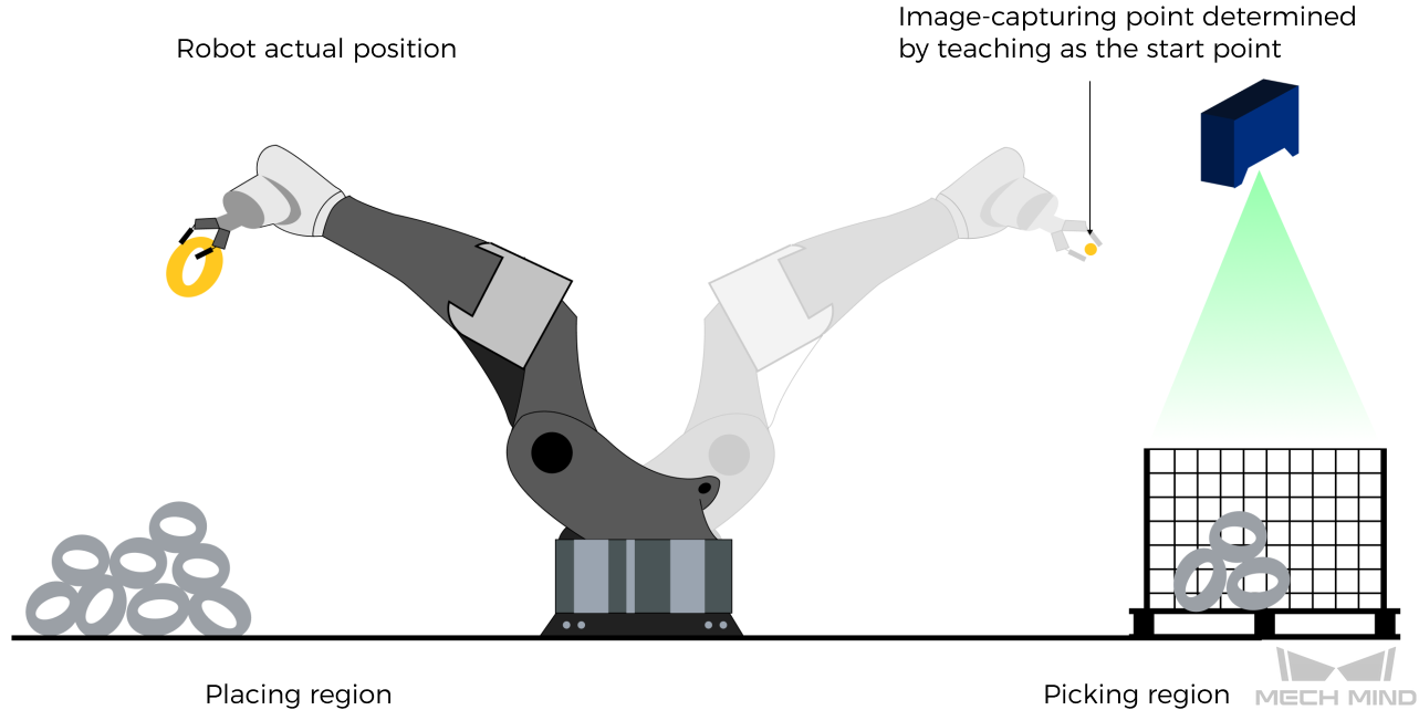
The robot JPs of a point determined by teaching must be input to Mech-Viz. The input JPs are used to trigger Mech-Viz to plan the next path in advance while the robot is not in the camera capture region, as shown below. The simulated robot in Mech-Viz moves from the input JPs to the first waypoint.
This setting is recommended for projects in the eye-to-hand mode.
The reason for setting robot pose type to 2 when the project is in the eye-to-hand mode:
In the eye-to-hand mode, the camera can perform image capturing for the next round of path planning before the robot returns to the camera capture region and picking region, shortening the cycle time.
If robot pose type is set to 1, the robot’s current pose is sent to Mech-Viz. The simulated robot will move from the input pose to the first waypoint in the planned path, while the real robot might move to another point first, and then move to the first waypoint. Therefore, the path of the real robot may contain unpredicted collisions, leading to safety hazards.
In conclusion, robot pose type should be set to 2 for projects in the eye-to-hand mode.
Data Returned
Parameter |
DB offset |
|---|---|
Status code |
200.0 |
Status code
If there is no error, status code 2103 will be returned. Otherwise, the corresponding error code will be returned.
Command 202: Stop Mech-Viz Project
This command stops the running of the Mech-Viz project. This command is needed only when the Mech-Viz project falls into an infinite loop or cannot be stopped normally.
Command Sent
Parameter |
DB offset |
|---|---|
Command code 202 |
2.0 |
Data Returned
Parameter |
DB offset |
|---|---|
Status code |
200.0 |
Status code
If there is no error, status code 2104 will be returned. Otherwise, the corresponding error code will be returned.
Command 203: Select Mech-Viz Branch
This command specifies which branch the project should run along. For this command, the branching is implemented by a Branch by Msg Step, and this command selects the branch by specifying an exit port of the Step.
Before executing this command, the Mech-Viz project needs to be started by executing command 201.
When the Mech-Viz project runs to the Branch by Msg Step, it will wait for command 203 to specify which exit port of the Step, i.e., the branch, the project should run along.
Command Sent
Parameter |
DB offset |
|---|---|
Command code 203 |
2.0 |
Branching Step ID |
60.0 |
Exit port number |
62.0 |
Branching Step ID
This parameter is for specifying which Branch by Msg Step the branch selection should apply to.
The Step ID can be read in the Step’s parameters.
Exit port number
This parameter is for specifying which exit port of the specified Step, i.e., the branch, the project should run along. The value should be an integer ([1, N]).
Note
An exit port number is the 1-based index of the specified exit port on the Step. For example, if the specified exit port is the second exit port of the Step from left to right, the exit port number is 2.
Data Returned
Parameter |
DB offset |
|---|---|
Status code |
200.0 |
Status code
If there is no error, status code 2105 will be returned. Otherwise, the corresponding error code will be returned.
Command 204: Set Move Index
This command is for setting the index parameter of a Step that involves sequential or separate motions or operations.
Steps with index parameters include Move by List, Move by Grid, Custom Pallet Pattern, Smart Pallet Pattern, etc.
Before executing this command, command 201 needs to be executed to start the Mech-Viz project.
Command Sent
Parameter |
DB offset |
|---|---|
Command code 204 |
2.0 |
Step ID |
64.0 |
Index value |
66.0 |
Step ID
This parameter specifies which Step the index setting should apply to.
The Step ID can be read in the Step’s parameters.
Index value
The index value that should be set the next time this Step is executed.
When this command is sent, the current index value in Mech-Viz will become the parameter value minus 1.
When the Mech-Viz project runs to the Step specified by this command, the current index value in Mech-Viz will be increased by 1 to become the parameter’s value.
Data Returned
Parameter |
DB offset |
|---|---|
Status code |
200.0 |
Status code
If there is no error, status code 2106 will be returned. Otherwise, the corresponding error code will be returned.
Command 205: Get Planned Path
This command gets the robot motion path planned by Mech-Viz after command 201 is executed to start the Mech-Viz project.
Note
If one of the waypoints in the path is not supposed to be sent to the robot, please clear the parameter Send Waypoint checkbox of the corresponding move-type Step.
Command Sent
Parameter |
DB offset |
|---|---|
Command code 205 |
2.0 |
Waypoint pose type |
4.0 |
Waypoint pose type type
This parameter specifies the type of waypoint poses to return from Mech-Viz.
1The waypoint poses returned should be in JPs.
2The waypoint poses returned should be in TCP.
Data Returned
Parameter |
DB offset |
|---|---|
Status code |
200.0 |
Data transmission status |
202.0 |
Number of waypoints |
204.0 |
Position of “Vision Move” |
206.0 |
All waypoint poses sent this time |
208.0 |
All waypoint labels sent this time |
1168.0 |
All waypoint velocities sent this time |
1248.0 |
Status code
If there is no error, status code 2100 will be returned. Otherwise, the corresponding error code will be returned.
Note
When executing this command, if Mech-Viz has not yet had the planned robot motion path (the project is still running), this command will wait before sending the results to the robot. The default wait time is 10 seconds. If a timeout occurs, the timeout error status code will be returned.
Data transmission status
This parameter indicates whether the data returned includes newly arrived waypoints.
1The waypoints in the data returned are new data.
After PLC reads all the waypoint data (poses, labels, velocities), please reset this field.
Note
By default, executing command 205 once can fetch at most 20 waypoints (poses, labels, velocities) at a time. If the number of waypoints is greater than 20, please execute command 205 multiple times.
Number of waypoints
This parameter indicates the number of path waypoints ([pose, label, velocity]) sent by executing this command this time.
Default range: 0 to 20.
Position of “Vision Move”
The position of the Vision Move Step, i.e., the move to the vision pose (usually the pose for picking the object) in the entire robot motion path.
For example, if the path is composed of Steps Fixed-Point Move_1, Fixed-Point Move_2, Vision Move, Fixed-Point Move_3 sequentially, the position of Vision Move is 3.
If in the path there is no Vision Move Step, the returned value will be 0.
All waypoint poses sent this time
Each pose includes Cartesian coordinates (XYZ) and Euler angles (ABC), or JPs, according to the waypoint type set by this command.
All waypoint labels sent this time
A label is the integer label assigned to a pose. If in the Mech-Vision project, the labels are strings, they need to be mapped to integers before outputting from the Mech-Vision project using Step Label Mapping. If there are no labels in the Mech-Vision project, the label defaults to 0.
All waypoint velocities sent this time
A velocity is the non-zero velocity parameter percentage value for the corresponding move-type Step in Mech-Viz.
Command 206: Get DO List
This command gets the planned DO signal list when there are multiple grippers, such as suction cup sections, to control.
For using this command:
In the parameters of the “Set DO List” Step:
Check “StandardInterface” under “Receiver”
Check “Get DO List from VisualMove”
Select a “Vision Move” Step that needs the DO signal list at the bottom of the parameter panel
Before calling this command, command 205 needs to be executed to obtain the planned motion path by Mech-Viz.
Please deploy the Mech-Viz project based on the template project at xxx\Mech-Mind Software Suite-x.x.x\Mech-Center\tool\viz_project\suction_zone, and set the suction cup configuration file in the Mech-Viz project.
Data Returned
Parameter |
DB offset |
|---|---|
Status code |
200.0 |
DO signals |
1408.0 |
Status code
If there are no errors, status code 2102 will be returned. Otherwise, the corresponding error code will be returned.
DO signal value
There are 64 DO signal values, in integers, located at the tail of the data returned.
Range of valid DO values: [0, 999]. Placeholder value: -1.
Command 501: Input Object Dimensions to Mech-Vision
This command is for dynamically inputting object dimensions into the Mech-Vision project.
Please confirm the actual object dimensions before running the Mech-Vision project.
The Mech-Vision project should have the Read Object Dimensions Step, and the Step’s parameter Read Sizes from Properties should be checked.
Command Sent
Parameter |
DB offset |
|---|---|
Command code 501 |
2.0 |
Project number |
8.0 |
[length, height, width] |
68.0 |
Project number
The integer ID number of the Mech-Vision project, displayed in the Project List panel in Mech-Vision. The ID number can be adjusted by dragging the projects.
[length, height, width]
The object dimensions to input to the Mech-Vision project.
Those values will be read by the Read Object Dimensions Step.
Unit: mm
Data Returned
Parameter |
DB offset |
|---|---|
Status code |
200.0 |
Status code
If there is no error, status code 1108 will be returned. Otherwise, the corresponding error code will be returned.
Command 502: Input TCP to Mech-Viz
This command is for dynamically inputting robot TCP into the Mech-Viz project.
The Step that receives the robot TCP is External Move.
Please deploy the Mech-Viz project based on the template project at xxx\Mech-Mind Software Suite-x.x.x\Mech-Center\tool\viz_project\outer_move, and put the External Move Step to a proper position in the workflow.
This command needs to be executed before executing command 201.
Command Sent
Parameter |
DB offset |
|---|---|
Command code 502 |
2.0 |
TCP |
80.0 |
Robot TCP
The TCP data used to set the waypoint for the Step External Move.
Data Returned
Parameter |
DB offset |
|---|---|
Status code |
200.0 |
Status code
If there is no error, status code 2107 will be returned. Otherwise, the corresponding error code will be returned.
Command 901: Get Software Status
This command is designed for checking the software running status of Mech-Vision, Mech-Viz, and Mech-Center. At present, this command only supports checking whether Mech-Vision is ready for running the project.
Data Returned
Parameter |
DB offset |
|---|---|
Status code |
200.0 |
Status code
Software status. 1101 means the Mech-Vision project is ready to run. Other codes mean the project is not ready.