TCP/IP
This topic introduces the Standard Interface commands according to the TCP/IP protocol.
The commands are as follows:
Command 101: Start Mech-Vision Project
This command starts the running of the Mech-Vision project, which executes image capturing and performs vision recognition.
If the project works in the eye-in-hand mode, the robot pose for image capturing needs to be transmitted by this command into the project.
This command is for scenarios using only Mech-Vision.
Command Sent
101, project number, expected number of vision points, robot pose type, robot pose
Project number
The integer ID number of the Mech-Vision project, displayed in the Project List panel in Mech-Vision. The ID number can be adjusted by dragging the projects.
Expected number of vision points
The number of vision points (i.e., vision poses and their corresponding point clouds, labels, indices, etc.) to expect Mech-Vision to output.
0: Get all the vision points from the Mech-Vision project’s recognition results.
integer > 0: Get the specified number of vision points.
If the total number of vision points is smaller than the parameter value, all the available vision points will be returned.
If the total number of vision points is greater than or equal to the parameter value, vision points in the quantity of the parameter value will be returned.
Note
The command to obtain the vision points is command 102. In TCP/IP, due to the limit that a maximum of 20 vision points can be obtained by executing command 102 at a time, after executing command 102 for the first time, one of the parameters returned will indicate whether all the vision points requested have been returned; if not, please repeat executing command 102.
Robot pose type and robot pose
Robot pose type indicates the type of pose of the real robot to input to Mech-Vision. The value range is 0–3.
The value of robot pose depends on the value of robot pose type.
The following table explains the relationship between the two parameters.
Robot pose type value
Robot pose value
Description
Applicable scenario
0
0, 0, 0, 0, 0, 0
No need to input robot pose to Mech-Vision.
Project is in the eye-to-hand mode. If the “Path Planning” Step is used, the planned path starts at the Home point set in the path planning tool.
1
Current JPs and flange pose of the robot
Robot JPs and flange pose must be input to Mech-Vision as the image-capturing pose.
Project is in the eye-in-hand mode. Applicable to most robots (excluding truss robots).
2
Current flange pose of the robot
Robot flange pose must be input to Mech-Vision as the image-capturing pose.
Project is in the eye-in-hand mode. The robot has no JPs and only flange pose (such as truss robots).
3
JPs of the start point of the planned path
The JPs of the path start point must be input to Mech-Vision.
Project is in the eye-to-hand mode and the Mech-Vision project contains the “Path Planning” Step, whose start point needs to be set from the robot side.
Hint
A pose is composed of position and orientation. The unit of the position is mm, and the orientation is represented by Euler’s angles, whose unit is degree (°). The unit of JPs is degree (°).
Data Returned
101, status code
Status code
If there is no error, status code 1102 will be returned. Otherwise, the corresponding error code will be returned.
Test Samples
In the eye-in-hand mode, the command is executed without error, and the current JPs and flange pose of the robot are sent.
TCP send string = 101, 1, 0, 1, 5.18, 14.52, 4.03, 0.09, 72.44, 5.15, 549.56, 50.0, 647.01, 180.0, -1.0, 180.0
TCP received string = 101, 1102
In the eye-to-hand mode, the command is executed without error, and the JPs of the path start point determined by teaching are sent.
TCP send string = 101, 1, 0, 3, 5.18, 14.52, 4.03, 0.09, 72.44, 5.15
TCP received string = 101, 1102
Error: project ID number does not exist.
TCP send string = 101, 2, 10, 0
TCP received string = 101, 1011
Command 102: Get Vision Target(s)
This command is called after Command 101: Start Mech-Vision Project to obtain the vision points output by Mech-Vision and transform the vision points to vision targets.
The transformation process is as follows:
Rotate the poses around their Y axes by 180 degrees.
Determine whether the definition of the reference frame used by the robot model involves robot base height, and add a vertical offset accordingly.
Note
In TCP/IP, by default, command 102 can only fetch at most 20 vision targets at a time. Therefore, command 102 may need to be repeatedly executed until all the vision targets required are obtained.
Command Sent
102, project number
Project number
The integer ID number of the Mech-Vision project, displayed in the Project List panel in Mech-Vision. The ID number can be adjusted by dragging the projects.
Data Returned
102, status code, transmission completion status, number of vision targets, reserved field, vision target, vision target, …, vision target
Note
The vision targets (up to 20 targets by default) are located at the tail of the data returned. A vision target contains the TCP, label and velocity, and the value of velocity is 0.
Status code
If there is no error, status code 1100 will be returned. Otherwise, the corresponding error code will be returned.
After executing this command, if the results from Mech-Vision have not been returned, this command will wait before sending the results to the robot. The default wait time is 10 seconds. If a timeout occurs, the timeout error status code will be returned.
Transmission completion status
This parameter indicates whether all the vision targets requested have been obtained.
0: Not all the vision targets requested have been obtained. Please repeat executing command 102 until this parameter turns 1.
1: All the vision targets requested have been obtained.Note
If not all the vision targets requested have been obtained and command 101 is executed at this time, the rest of the vision targets that are not obtained will be cleared.
Number of vision targets
The number of vision targets obtained by executing this command this time.
Reserved field
This field is not used.
The value defaults to 0.
Target
A vision target is composed of 8 data: the first 6 data are the pose in the form of TCP, the 7th data is the label, and the 8th data is the velocity.
Pose: A pose in the form of TCP includes the Cartesian coordinates (XYZ) and Euler angles (ABC).
Label: The integer label assigned to the pose. If in the Mech-Vision project, the labels are strings, they need to be mapped to integers before outputting from the Mech-Vision project using Step Label Mapping. If there are no labels in the Mech-Vision project, the label defaults to 0.
Velocity: The parameter defaults to 0 for command 102 because Mech-Vision does not plan robot target velocity.
Test Samples
Test samples of normal execution and execution error
Command 102 is executed without error.
TCP send string = 102, 1
TCP received string = 102, 1100, 1, 1, 0, 95.7806085592122, 644.5677779910724, 401.1013614123109, 91.12068316085427, -171.13014981284968, 180.0, 0, 0
Error: no vision result.
TCP send string = 102, 1
TCP received string = 102, 1002
Test Sample of requesting targets
The test sample below is obtaining 22 vision targets by sending commands 101, 102, and 102 sequentially. Details are as follows:
TCP/IP sends command 101, with content
101, 1, 0, 1, …, expecting to obtain all the available vision targets.TCP/IP sends command 102 to obtain part of the vision targets.
TCP/IP receives the data returned by executing command 102. The content is
102, 1100, 0, 20, …, indicating 20 vision targets have been obtained and not all targets have been obtained.TCP/IP sends command 102 again to fetch the remaining vision targets.
TCP/IP receives the data returned by executing command 102 again. The content is
102, 1100, 1, 2, ..., which includes 2 vision targets and indicates all the targets have been obtained.
Send command 101.
TCP send string = 101, 1, 0, 1, -0, -20.63239, -107.81205, -0, -92.81818, 0.0016
TCP received strins = 101, 1102
Send command 102 for the first time and obtain the first 20 vision targets.
TCP send string = 102, 1

TCP received string = 102, 1100, 0, 20, 0, 95.7806085592122, 644.5677779910724, 401.1013614123108, 31.12068316085427, ...
TCP received string = 78549940546, -179.99999999999991.0.0, 329.228345202334.712.7061697180302.400.9702665047771, ...
TCP received string =39546, -83.62567351596952, -170.87955974536686, -179.99999999999937, 0, 0, 223.37118373658322, ...
TCP received string = 005627, 710.1004355953408, 400.82227273918835, -43.89328326393665, -171.30845207792612, ...
TCP received string = 20.86318821742358, 838.7634193547805, 400.79807564314797, -102.03947940869523, -171.149261231 ...
TCP received string = 390299920645, -179.99999999999994, 0, 0, 303.0722145720921, 785.3254917220695, 400.75827437080, ...
TCP received string = 99668287.77.78291612041707, -171.53941633937786, 179.99999999899997, 0.0, 171.47819668864432, ...
TCP received string = 332193785, 400.6472716208158, -94.3418019038759, -171.10001228964776, -179.39999999999994, ...
TCP received string = 92388542936, 807.5641001485708, 400.6021999602664, - 167.9834797197932.-171.39671274951826, ...
TCP received string = 278.3198007132188, 780.5325992145735, 400.4924381003066, -174.72728396633053, -171.422604771 ...
TCP received string = 3.99999999999994, 0, 0, 183.82195326381233, 862.5171519967056.400.422966515846.-154. 17801945 ...
TCP received string = 173.34301974982765, -180.0, 0, 0
Send command 102 for the second time and obtain the last 2 vision targets.
TCP send string = 102, 1

TCP received string = 102, 1100, 1, 2, 0, 315.2017788478321, 592.1261793743445, 399.60526335590957, 126.19602189220371, ...
TCP received string = 686127, -171.44430002882129, -1.3381805753922965e-15, 0, 0
Command 103: Switch Mech-Vision Recipe
This command switches the parameter recipe used by the Mech-Vision project.
In Mech-Vision, you can change the settings of a group of parameters by switching the parameter recipe.
Parameters involved in recipe switching usually include point cloud matching model, image matching template, ROI, confidence threshold, etc.
This command needs to be used before executing command 101 which starts the Mech-Vision project.
Command Sent
103, project number, recipe number
Project number
The integer ID number of the Mech-Vision project, displayed in the Project List panel in Mech-Vision. The ID number can be adjusted by dragging the projects.
Recipe number
The ID number of the parameter recipe to switch to, i.e., the number on the left of the parameter recipe name in in Mech-Vision.
Recipe number range: 1–99.
Data Returned
103, status code
Status code
If there is no error, status code 1107 will be returned. Otherwise, the corresponding error code will be returned.
Test Samples
Command 103 is executed normally without errors.
TCP send string = 103, 1, 2
TCP received string = 103, 1107
Error: invalid recipe number.
TCP send string = 103, 1, 2
TCP received string = 103, 1102
Command 105: Get Result of Step “Path Planning” in Mech-Vision
This command gets the collision-free path planning result of the “Path Planning” Step in Mech-Vision, after executing command 101.
When using this command, the Port Type parameter of the “Procedure Out” Step must be set to Predefined (robot path).
Hint
Before executing command 105, please set expected number of vision points of command 101 to 0 to reduce the times of execution of command 105. If expected number of vision points of command 101 is set to 1, then every time command 105 is executed, only 1 waypoint is returned, and command 105 must be executed multiple times to obtain all the waypoints.
Command Sent
105, project number, waypoint pose type
Project number
The integer ID number of the Mech-Vision project, displayed in the Project List panel in Mech-Vision. The ID number can be adjusted by dragging the projects.
Waypoint type
The type of waypoint pose returned by the “Path Planning” Step.
1: The waypoint poses are returned in the form of JPs.
2: The waypoint poses are returned in the form of TCP.
Data Returned
105, status code, transmission completion status, number of waypoints, position of “Vision Move”, waypoint, waypoint, …, waypoint
Status code
If there is no error, status code 1103 will be returned. Otherwise, the corresponding error code will be returned.
Transmission completion status
This parameter indicates whether all the waypoints requested have been obtained.
0: Not all the waypoints in the planned path have been obtained. Please repeat executing command 105 until this parameter turns 1.
1: All the waypoints in the planned path have been obtained.
Number of waypoints
The number of waypoints obtained by executing this command this time. The value range is 0–20. If the planned path contains more than 20 waypoints, please repeat executing command 105.
Position of “Vision Move”
The position of the Vision Move Step, i.e., the move to the vision pose (usually the pose for picking the object) in the entire robot motion path.
For example, if the path is composed of Steps Fixed-Point Move_1, Fixed-Point Move_2, Vision Move, Fixed-Point Move_3 sequentially, the position of Vision Move is 3.
If in the path there is no Vision Move Step, the returned value will be 0.
Waypoint
A waypoint is composed of 8 data: the first 6 data are the pose, the 7th data is the label, and the 8th data is the velocity.
Pose: the Cartesian coordinates (XYZ in mm) and Euler angles (ABC in degree), or JPs (in degree). The type is determined by the waypoint type parameter in command 105.
Label: The integer label assigned to the pose. If in the Mech-Vision project, the labels are strings, they need to be mapped to integers before outputting from the Mech-Vision project using Step Label Mapping. If there are no labels in the Mech-Vision project, the label defaults to 0.
Velocity: The velocity set in the path planning tool.
Test Samples
Command 105 is executed normally without errors.
TCP send string = 105, 1, 2
TCP received string =105,1103,1,5,3,1030.0,0,1260.0,0.0,90.0,-0.0,0,7,1149.114,-298.9656,274.9219,-0.0977,-1.3863,-175.9702,0,7,1149.8416,-296.8585,245.0048,-0.0977,-1.3863,-175.9702,2,7,1149.114,-298.9656,274.9219,-0.0977,-1.3863,-175.9702,0,7,1030.0,0,1260.0,0.0,90.0,-0.0,0,7
Error: all pose already transmitted.
TCP send string = 105, 1,2
TCP received strins = 105, 1020
Command 110: Get Custom Output Data from Mech-Vision
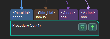
This command is for receiving custom data, i.e., data other than poses and labels, from Step “Procedure Out” in Mech-Vision (when the parameter “Port Type” is set to “Custom”).
Executing this command once only fetches one pose and its corresponding labels, scores, etc. (if any) from the vision result. If expecting to receive multiple poses, please execute this command multiple times.
Command Sent
110, project number
Project number
The integer ID number of the Mech-Vision project, displayed in the Project List panel in Mech-Vision. The ID number can be adjusted by dragging the projects.
Data Returned
110, status code, pose transmission completion status, number of custom data items, robot TCP transformed from object pose, label, custom data items, …, custom data items
Status code
If there is no error, status code 1100 will be returned. Otherwise, the corresponding error code will be returned.
After executing this command, if the results from Mech-Vision have not been returned, this command will wait before sending the results to the robot. The default wait time is 10 seconds. If a timeout occurs, the timeout error status code will be returned.
pose transmission completion status
0: Not all poses in the vision result have been transmitted.
1: All poses in the vision result have been transmitted.
Number of custom data items
The total number of custom data items of data types other than poses and labels.
For example, if aaa is a list with 3 items and bbb is a list with 3 items, when executing this command to fetch one item from each list, the parameter value is 1+1=2; if aaa and bbb are both single variables, the parameter value is still 1+1=2.
Pose
The TCP under the robot frame. The object pose output by Mech-Vision and the pose is transformed into robot TCP. Step “Procedure Out” must have a port for poses.
A TCP for an object pose is usually generated by flipping the z-axis of the object pose.
Label
Object info label corresponding to the pose. The label should be a positive integer. If not, it should be mapped to a positive integer in the Mech-Vision project by Step Label Mapping. If there is no port for labels on Step “Procedure Out”, the field is filled with 0.
Custom data
The custom data for the corresponding port of custom data type on Step “Procedure Out”.
The custom data parameters are arranged in alphabetical order A–Z by port name.
Command 201: Start Mech-Viz Project
This command is for scenarios using both Mech-Vision and Mech-Viz.
This command starts the running of the Mech-Viz project, calls the corresponding Mech-Vision project, and lets the Mech-Viz project plan the robot path based on the vision points from Mech-Vision.
For the Mech-Viz project that needs to be started, the option Autoload needs to be checked in Mech-Viz’s interface.
Please see Example Mech-Viz Projects for Standard Interface for the description of example Mech-Viz projects.
Command Sent
201, robot pose type, robot pose
Robot pose type and robot pose
Robot pose type indicates the type of the robot pose of the real robot to input to Mech-Viz. The value range is 0–2.
The value of robot pose depends on the value of robot pose type.
The following table explains the relationship between the two parameters.
Robot pose type value
Robot pose value
Description
Applicable scenario
0
0, 0, 0, 0, 0, 0
No need to input robot pose to Mech-Viz. The simulated robot in Mech-Viz moves from JPs = [0, 0, 0, 0, 0, 0] to the first waypoint.
Project is in the eye-to-hand mode. This setting is not recommended.
1
Current JPs and flange pose of the robot
Robot JPs and flange pose must be input to Mech-Viz. The simulated robot in Mech-Viz moves from the input JPs to the first waypoint.
This setting is recommended for projects in the eye-in-hand mode.
2
Specific JPs of the robot
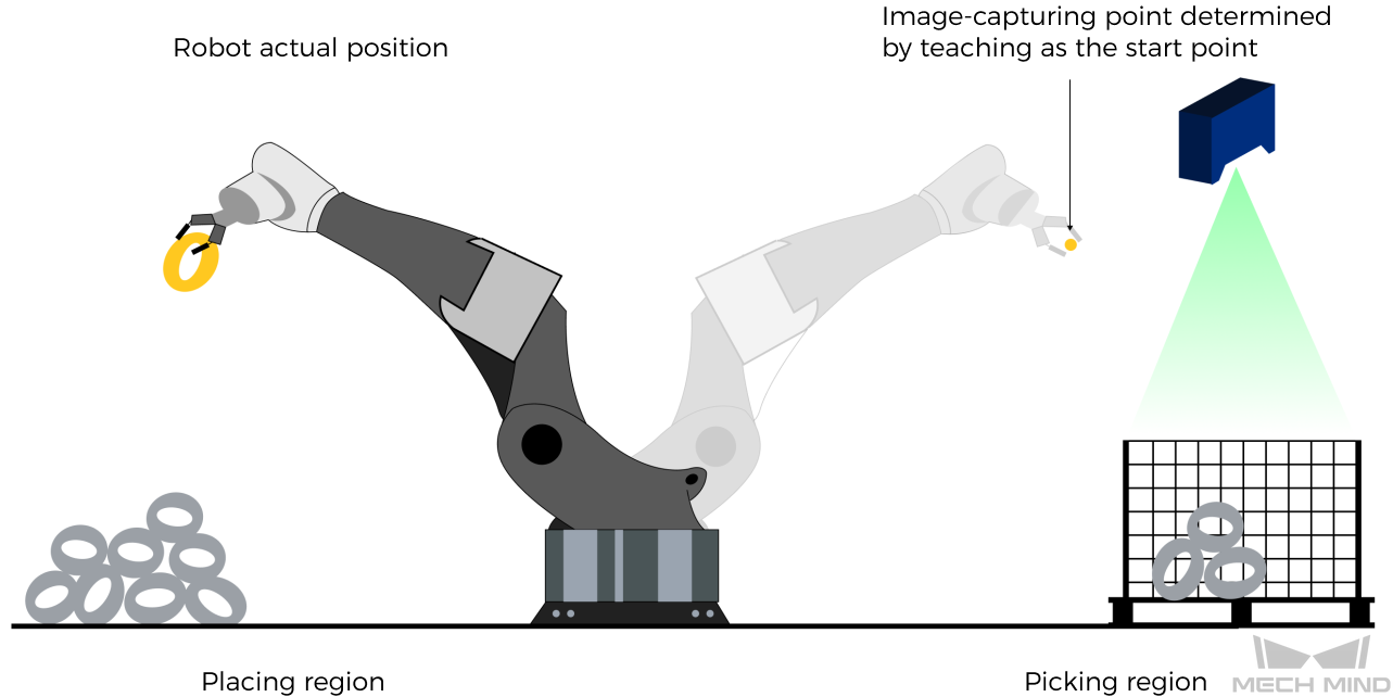
The robot JPs of a point determined by teaching must be input to Mech-Viz. The input JPs are used to trigger Mech-Viz to plan the next path in advance while the robot is not in the camera capture region, as shown below. The simulated robot in Mech-Viz moves from the input JPs to the first waypoint.
This setting is recommended for projects in the eye-to-hand mode.
The reason for setting robot pose type to 2 when the project is in the eye-to-hand mode:
In the eye-to-hand mode, the camera can perform image capturing for the next round of path planning before the robot returns to the camera capture region and picking region, shortening the cycle time.
If robot pose type is set to 1, the robot’s current pose is sent to Mech-Viz. The simulated robot will move from the input pose to the first waypoint in the planned path, while the real robot might move to another point first, and then move to the first waypoint. Therefore, the path of the real robot may contain unpredicted collisions, leading to safety hazards.
In conclusion, robot pose type should be set to 2 for projects in the eye-to-hand mode.
Hint
A pose is composed of position and orientation. The unit of the position is mm, and the orientation is represented by Euler’s angles, whose unit is degree (°). The unit of JPs is degree (°).
Data Returned
201, status code
Status code
If there is no error, status code 2103 will be returned. Otherwise, the corresponding error code will be returned.
Test Samples
In the eye-in-hand mode, the command is executed without error, and the current JPs and flange pose of the robot are sent.
TCP send string = 201, 1, 5.18, 14.52, 4.03, 0.09, 72.44, 5.15, 549.56, 50.0, 647.01, 180.0, -1.0, 180.0
TCP received string = 201, 2103
In the eye-to-hand mode, the command is executed without error, and the JPs of the path start point determined by teaching are sent.
TCP send string = 201, 2, 5.18, 14.52, 4.03, 0.09, 72.44, 5.15
TCP received string = 201, 2103
Error: the requested pose data are not sent.
TCP send string = 201, 1
TCP received string = 201, 2013
Command 201 is executed without error.
TCP send string = 201, 1, 0, -20.63239, -107.81205, 0, -92.81818, 0.00307
TCP received string = 201, 2103
Error: Mech-Viz does not support robot pose in TCP.
TCP send string = 201, 2, -0, 682.70355, 665.22266, 90, 179.99785, -89.99693
TCP received string = 201, 2015, 1
Command 202: Stop Mech-Viz Project
This command stops the running of the Mech-Viz project. This command is needed only when the Mech-Viz project falls into an infinite loop or cannot be stopped normally.
Command Sent
202
Data Returned
202, status code
Status code
If there is no error, status code 2104 will be returned. Otherwise, the corresponding error code will be returned.
Test Sample
Command 202 is normally executed.
TCP send string = 202
TCP received string = 202, 2104
Command 203: Select Mech-Viz Branch
This command specifies which branch the project should run along. For this command, the branching is implemented by a Branch by Msg Step, and this command selects the branch by specifying an exit port of the Step.
Before executing this command, the Mech-Viz project needs to be started by executing command 201.
When the Mech-Viz project runs to the Branch by Msg Step, it will wait for command 203 to specify which exit port of the Step, i.e., the branch, the project should run along.
Command Sent
203, branching Step ID, exit port number
Branching Step ID
The Step ID of the Branch by Msg Step.
This parameter is for specifying which Branch by Msg Step the branch selection should apply to.
The Step ID can be read in the Step’s parameters.
Exit port number
This parameter is for specifying which exit port of the specified Step, i.e., the branch, the project should run along. The value should be an integer ([1, N]).
Note
An exit port number is the 1-based index of the specified exit port on the Step. For example, if the specified exit port is the second exit port of the Step from left to right, the exit port number is 2.
Data Returned
203, status code
Status code
If there is no error, status code 2105 will be returned. Otherwise, the corresponding error code will be returned.
Test Samples
Command 203 is executed normally without errors.
TOP send string = 203, 1, 1
TCP received string = 203, 2105
Error: invalid exit port number.
TCP send string = 203, 1, 3
TCP received string = 203, 2018
Command 204: Set Move Index
This command is for setting the index parameter of a Step that involves sequential or separate motions or operations.
Steps with index parameters include Move by List, Move by Grid, Custom Pallet Pattern, Smart Pallet Pattern, etc.
Before executing this command, command 201 needs to be executed to start the Mech-Viz project.
Command Sent
204, Step ID, index value
Step ID
This parameter specifies which Step the index setting should apply to.
The Step ID can be read in the Step’s parameters.
Index value
The index value that should be set the next time this Step is executed.
When this command is sent, the current index value in Mech-Viz will become the parameter value minus 1.
When the Mech-Viz project runs to the Step specified by this command, the current index value in Mech-Viz will be increased by 1 to become the parameter’s value.
Data Returned
204, status code
Status code
If there is no error, status code 2106 will be returned. Otherwise, the corresponding error code will be returned.
Test Samples
Command 204 is executed normally without errors.
TCP send string = 204, 2, 6
TCP received string = 204, 2106
Error: Failed to set the index.
TCP send string = 204, 3, 6
TCP received string = 204, 2028
Command 205: Get Planned Path
This command gets the robot motion path planned by Mech-Viz after command 201 is executed to start the Mech-Viz project.
Note
In TCP/IP, by default, command 205 can only fetch at most 20 waypoints of the planned path at a time. So, command 205 may need to be executed repeatedly until all the waypoints required are obtained.
Note
If one of the waypoints in the path is not supposed to be sent to the robot, please clear the parameter Send Waypoint checkbox of the corresponding move-type Step.
Command Sent
205, waypoint pose type
Waypoint pose type
This parameter specifies the type of waypoint poses to return from Mech-Viz.
1: The waypoint poses returned should be in JPs.
2: The waypoint poses returned should be in TCP.
Data Returned
205, status code, transmission completion status, number of waypoints, position of “Vision Move”, waypoint, waypoint, …
Status code
If there is no error, status code 2100 will be returned. Otherwise, the corresponding error code will be returned.
Note
When executing this command, if Mech-Viz has not yet had the planned robot motion path (the project is still running), this command will wait before sending the results to the robot. The default wait time is 10 seconds. If a timeout occurs, the timeout error status code will be returned.
Transmission completion status
0: Not all the waypoints of the planned path have been obtained. Please repeat executing this command until this parameter’s value is 1.
1: All the waypoints of the planned path have been obtained.Note
If the expected number of waypoints to transmit is greater than 20 (20 is the default setting), please execute command 205 multiple times until the returned value of this parameter is 1.
Number of waypoints
This parameter indicates the number of path waypoints ([pose, label, velocity]) sent by executing this command this time.
Default range: 0 to 20.
Position of “Vision Move”
The position of the Vision Move Step, i.e., the move to the vision pose (usually the pose for picking the object) in the entire robot motion path.
For example, if the path is composed of Steps Fixed-Point Move_1, Fixed-Point Move_2, Vision Move, Fixed-Point Move_3 sequentially, the position of Vision Move is 3.
If in the path there is no Vision Move Step, the returned value will be 0.
Waypoint
A waypoint is composed of 8 data: the first 6 data are the pose, the 7th data is the label, and the 8th data is the velocity.
Pose: the Cartesian coordinates (XYZ in mm) and Euler angles (ABC in degree), or JPs (in degree). The type is determined by the waypoint type parameter in command 205.
Label: The integer label assigned to the pose. If in the Mech-Vision project, the labels are strings, they need to be mapped to integers before outputting from the Mech-Vision project using Step Label Mapping. If there are no labels in the Mech-Vision project, the label defaults to 0.
Velocity: The non-zero velocity parameter percentage value for the move-type Step set in Mech-Viz.
Test Samples
Command 205 is executed without error.
TCP send string = 205, 1

TCP received string =205, 2100, 1, 2, 2, 8.307755332057372, 15.163476541700463, -142.1778810972881, -2.7756047848536745, -31.44046012182799, -96.94907235126934, 0, 64, 8.2 42574265592342, 12.130080796661591, -141.75872288706663-2.513533225987894, -34.8905853 039525, -97.19108378871277, 0, 32
Error: Mech-Vision runtime error.
TCP send string = 205, 1
TCP received string = 205, 2008
Command 206: Get DO List
This command gets the planned DO signal list when there are multiple grippers, such as suction cup sections, to control.
For using this command:
In the parameters of the “Set DO List” Step:
Check “StandardInterface” under “Receiver”
Check “Get DO List from VisualMove”
Select a “Vision Move” Step that needs the DO signal list at the bottom of the parameter panel
Before calling this command, command 205 needs to be executed to obtain the planned motion path by Mech-Viz.
Please deploy the Mech-Viz project based on the template project at xxx\Mech-Mind Software Suite-x.x.x\Mech-Center\tool||viz_project\suction_zone, and set the suction cup configuration file in the Mech-Viz project.
Data Returned
206, status code, DO signal value, DO signal value, ..., DO signal value
Status code
If there are no errors, status code 2102 will be returned. Otherwise, the corresponding error code will be returned.
DO signal value
There are 64 DO signal values, in integers, located at the tail of the data returned.
Range of valid DO values: [0, 999]. Placeholder value: -1.
Test Samples
Command 206 is normally executed. The obtained DO signal values: 11, 12.
TCP send string: 206
TCP receive string: 206, 2102, 11, 12, -1, -1, -1, -1, -1, -1, -1, -1, -1, -1, -1, -1, -1, -1, -1, -1, -1, -1, -1, -1, -1, -1, -1, -1, -1, -1, -1, -1, -1, -1, -1, -1, -1, -1, -1, -1, -1, -1, -1, -1, -1, -1, -1, -1, -1, -1, -1, -1, -1, -1, -1, -1, -1, -1, -1, -1, -1, -1, -1, -1, -1, -1
Error: Mech-Viz did not provide a valid DO signal list.
TCP send string: 206
TCP receive string: 206, 2011, -1, -1, -1, -1, -1, -1, -1, -1, -1, -1, -1, -1, -1, -1, -1, -1, -1, -1, -1, -1, -1, -1, -1, -1, -1, -1, -1, -1, -1, -1, -1, -1, -1, -1, -1, -1, -1, -1, -1, -1, -1, -1, -1, -1, -1, -1, -1, -1, -1, -1, -1, -1, -1, -1, -1, -1, -1, -1, -1, -1, -1, -1, -1, -1
Command 207: Read Mech-Viz Step Parameter
This command reads the values of specified parameters of specified Steps. Please specify which parameters of which Steps to read in Property Config under in Mech-Center.
Command Sent
207, config ID
Config File Content Format
read, config ID, Step ID, parameter key name
The lines starting with “#” are comment lines and take no effect when executing this command.
read
The string “read” indicates the command is for reading the parameter value.
config ID
The positive integer number for specifying the ID of the read operation. A config ID can only be used for reading one parameter. If reading multiple parameters, please use different config IDs.
Step ID
The ID of the Step that the parameter to read belongs to.
The Step ID can be read in a Step’s parameters.
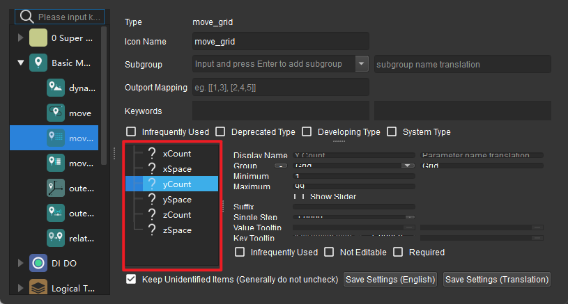
Parameter key name
The key name of the parameter to read. Please find the key name in in Mech-Viz, as shown in the figure below.
Config File Content Example
read, 1, 10, digitalOutValue
read, 2, 2, xCount
read, 3, 2, yCount
read, 4, 5, allowVisionResultUnused
write, 1, 3, xOffset, 0.000000
write, 1, 3, yOffset, 0.000000
write, 1, 3, zOffset, 0.000030
write, 2, 7, delayTime, 0.1
Data Returned
207, status code, Step parameter value
Status code
If there is no error, status code 2109 will be returned. Otherwise, the corresponding error code will be returned.
Step parameter value
The value of the specified parameter of the specified Step in the Mech-Viz project.
Data types supported: INT, FLOAT, STRING.
Test Samples
Command 207 is normally executed. The value of the specified Step parameter is obtained.
TCP send string = 207, 1
TCP received strins = 207, 2109, 10
Error: the specified parameter is not found.
TCP send string = 207, 1
TCP received strins = 207, 2041
Command 208: Set Mech-Viz Step Parameter
This command sets the values of specified parameters of specified Steps. Please specify what values and which parameters of which Steps to set in Property Config under .
Command Sent
208, config ID
Config File Content Format
write, config ID, Step ID, parameter key name, value
write
The string “write” indicates the command is for writing the parameter value.
config ID
The positive integer number for specifying the ID of the write operation.
A config ID can be used for reading multiple parameters.
Step ID
The ID of the Step that the parameter to write belongs to.
The Step ID can be read in a Step’s parameters.
Parameter key name
The key name of the parameter to read. Please find the key name in in Mech-Viz, as shown in the figure below.
Value
What value the specific parameter should be set at.
In addition to numbers, string values are also supported.
Config File Content Example
read, 1, 10, digitalOutValue
read, 2, 2, xCount
read, 3, 2, yCount
read, 4, 5, allowVisionResultUnused
write, 1, 3, xOffset, 0.000000
write, 1, 3, yOffset, 0.000000
write, 1, 3, zOffset, 0.000030
write, 2, 7, delayTime, 0.1
Data Returned
208, status code
If there is no error, status code 2108 will be returned. Otherwise, the corresponding error code will be returned.
Test Samples
Command 208 is normally executed. The specified Step parameter is set to the specified value.
TCP send string = 208, 1
TCP received strins = 208, 2108
Error: the specified parameter is not found.
TCP send string = 208, 10
TCP received strins = 208, 3008
Command 210: Get Waypoint with Vision Planning Result
This command is for getting a single planned waypoint from Mech-Viz. The waypoint may be a waypoint for a Vision Move Step, or a waypoint for one of the other move-type Steps. A waypoint may contain pose, velocity, gripper info, object info, etc.
A waypoint obtained by executing this command may be one of the following.
A waypoint of a move-type Step other than Vision Move, with info including the motion type (joint motion or linear motion), gripper ID, and velocity.
A waypoint of a Vision Move Step, with info including the label, the total number of workobjects picked, planned number of workobjects for the next multi-pick, suction cup corner ID, TCP offset, workobject orientation, workobject group dimensions.
A waypoint of a Vision Move Step, with info output from Step “Procedure Out” in the Mech-Vision project. If the port type of the Step is set to “Custom”, the waypoint will also include the custom data types.
Note
Usually, this command is used for projects in which the workobjects are boxes.
Note
Executing this command once only gets one waypoint. If expecting to obtain multiple waypoints, please execute this command multiple times.
Command Sent
210, expected data format
Expected data format
Below are four expected data formats for the waypoint and vision planning result.
JPs, motion type, gripper ID, velocity, number of custom ports, custom port output 1, …, custom port output N
TCP, motion type, gripper ID, velocity, number of custom ports, custom port output 1, …, custom port output N
JPs, motion type, gripper ID, velocity, number of custom ports, vision plan results, custom port output 1, …, custom port output N
TCP, motion type, gripper ID, velocity, number of custom ports, vision plan results, custom port output 1, …, custom port output N
Data Returned
210, status code, waypoint transmission completion status, waypoint type, pose, motion type, gripper ID, velocity, vision plan results *, number of custom ports, custom port outputs *
* Whether there are vision plan results and/or custom port outputs depends on the expected data format sent when executing the command.
Status code
If there is no error, status code 2100 will be returned. Otherwise, the corresponding error code will be returned.
Waypoint transmission completion status
0: Not all waypoints have been transmitted.
1: All waypoints have been transmitted.
Waypoint type
0: The waypoint is not a Vision Move Step waypoint.
1: The waypoint is a Vision Move Step.
Pose
The waypoint pose in JPs or TCP, depending on the parameter sent.
Motion type
1: joint motion, MOVEJ
2: linear motion, MOVEL
Gripper ID
The ID of the gripper used on the waypoint. -1 means no gripper is used.
Velocity
The percentage value of the velocity at the waypoint, i.e., the velocity set in the move-type Step in the Mech-Viz project.
Vision plan results
The planning result info in the waypoint (if the waypoint is a Vision Move waypoint). Usually used in carton multi-pick, depalletizing, etc. The info includes:
Labels: Object labels. Up to 10 positive integer labels are supported. The default values are zeros.
Total number of workobjects picked
Planned number of workobjects for the next multi-pick
Corner ID. The ID to indicate which corner of the gripper the workobjects are close to.
TCP offset: The offset from the original TCP on the workobject center to the actual TCP.
Orientation: The orientation of the workobject frame x-axis relative to the TCP x-axis.
Workobject dimensions.
Number of custom ports
The number of output keys excluding poses and labels when the Port Type parameter of the Procedure Out Step in the Mech-Vision project is set to “Custom”.
Custom port outputs
The outputs excluding poses and labels when the Port Type parameter of the Procedure Out Step in the Mech-Vision project is set to “Custom”.
The custom data parameters are arranged in alphabetical order A–Z by port name.
Command 501: Input Object Dimensions to Mech-Vision
This command is for dynamically inputting object dimensions into the Mech-Vision project.
Please confirm the actual object dimensions before running the Mech-Vision project.
The Mech-Vision project should have the Read Object Dimensions Step, and the Step’s parameter Read Sizes from Properties should be checked.
Command Sent
501, project number, length, height, width
Project number
The integer ID number of the Mech-Vision project, displayed in the Project List panel in Mech-Vision. The ID number can be adjusted by dragging the projects.
Length, height, width
The object dimensions to input to the Mech-Vision project.
These values will be read by the Read Object Dimensions Step.
Unit: mm
Data Returned
501, status code
Status code
If there is no error, status code 1108 will be returned. Otherwise, the corresponding error code will be returned.
Test Samples
Command 501 is executed without error.
TCP send string: 501, 1, 100, 200, 300
TCP receive string: 501, 1108
Error: Error code 3002, missing height value.
TCP send string: 501, 1, 100, 200
TCP receive string: 501, 3002
Command 502: Input TCP to Mech-Viz
This command is for dynamically inputting robot TCP into the Mech-Viz project.
The Step that receives the robot TCP is External Move.
Please deploy the Mech-Viz project based on the template project at xxx\Mech-Mind Software Suite-x.x.x\Mech-Center\tool\viz_project\outer_move, and put the External Move Step to a proper position in the workflow.
This command needs to be executed before executing command 201.
Data Returned
502, status code
Status code
If there is no error, status code 2107 will be returned. Otherwise, the corresponding error code will be returned.
Test Samples
Command 502 is executed without error.
TCP send string: 502, 0, 10, 10, 20, 0, 0
TCP received string: 502, 2107
Command 601: Notify
The user does not need to initiate this command.
When the Mech-Viz/Mech-Vision project runs to Step Notify or Step Notify, Standard Interface will send the custom notification message defined in Step Notify or Step Notify.
In Mech-Vision, Step Notify must be named “Standard Interface Notify”.
In Mech-Viz, in the parameters of Step Notify, please check “StandardInterface” under “Receiver”.
Command Sent
None
Data Returned
601, custom notification message
Custom notification message
The notification message defined in the Notify Step. The message must be an integer.
Test Sample
When the notification message defined in the Notify Step is set to integer 1000, the project will return 1000 when running through the Notify Step.
TCP receive string = 601, 1000
Command 701: Calibration
This command is for hand-eye calibration (camera extrinsic parameter calibration).
This command syncs the calibration status with Mech-Vision and fetches each calibration point that the robot needs to reach.
This command needs to be executed multiple times to complete the calibration.
Command Sent
701, calibration status, flange pose, JPs
Calibration status
0: Tell Mech-Vision to initiate the calibration.
1: The previous calibration point has been received by the robot.
2: The previous calibration point failed to be received by the robot.
Flange pose
The current flange pose of the robot. The flange pose is composed of position and orientation. The unit of the position is mm, and the orientation is represented by Euler’s angles, whose unit is degree (°).
JPs
The current JPs of the robot. The unit of JPs is degree (°).
Hint
You only need to specify either flange pose or JPs. Fill the other parameter with 6 zeros.
Data Returned
701, status code, calibration status, next calibration point’s flange pose, next calibration point’s JPs
Status code
This status code is for indicating the status of receiving the calibration point. If the calibration point is transmitted normally, status code 7101 will be returned. Otherwise, the corresponding error code will be returned.
Calibration status
1: Calibration is in progress.
0: Calibration finished.
Next calibration point’s flange pose
The flange pose of the next calibration point the robot should move to.
Next calibration point’s JPs
The JPs of the next calibration point the robot should move to.
Test Samples
Initiate the calibration.
TCP send string = 701, 0, 1371.62147, 25.6, 1334.3529, 148.58471, -179.24347, 88.75702, 88.86102, -7.11107, -28.82309, -0.44014, -67.6509, 31.4764
TCP received string = 701, 7101, 0, 1271.6969, -743374, 1334.34094, -3128422, 1792412, -91.11236, 93.28109, -12.0273, -32.8811, -0.37183, -68.41364, 27.02411
Obtain the calibration point from Mech-Vision (this process needs to be repeated to obtain multiple calibration points).
TCP send string = 701, 1, 1271.6969, -74.3374, 1334.34094, -3128422, 1792412, -91.11236, 93.28109, -12.0273, -32.8811, -0.37183, -68.41364, 27.02411
TCP received string = 701, 7101, 0, 1471.62226, -74.40452, 1334.34235, 148.56924, -179.24432, 88.74148, 92.8367, -2.14999, -24.25433, -0.39222, -67.23261, 27.485225
Finish the calibration.
TCP send string = 701, 1, 1371.60876, 25.53615, 1384.45532, -20.82704, 179.22026, -72.77879, 88.88467, -7.42242, -26.68142, -0.2991, -69.95593, 39.26262
TCP received string = 701, 7101, 1, 1371.62147, 25.6, 1334.3529, 148.58471, -179 24347, 88.75702, 88.86102, -7.11107, -28.82309, -0.44014, -67.6509, 31.4764
Command 901: Get Software Status
This command is designed for checking the software running status of Mech-Vision, Mech-Viz, and Mech-Center. At present, this command only supports checking whether Mech-Vision is ready for running the project.
Data Returned
901, status code
Status code
Software status. 1101 means the Mech-Vision project is ready to run. Other codes mean the project is not ready.
Test Samples
Mech-Vision is ready for running the project.
TCP send string = 901
TCP received string = 901, 1101
Mech-Vision is not ready for running the project. Please open the project in Mech-Vision, right-click on the project in Projects List, and check Autoload Project.
TCP send string = 901
TCP received string = 901, 1001