Modbus TCP - MELSEC-Q Series PLC Commands
This topic introduces the commands for Modebus TCP communication between a Mitsubishi MELSEC-Q Series PLC and Mech-Mind Software Suite. The detailed register map table is available in another section.
Commands
Start Mech-Vision Project
This command is for applications that use Mech-Vision but not Mech-Viz. It runs the corresponding Mech-Vision project to acquire and process data.
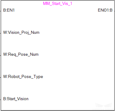
Parameters
Input parameters
Vision_Proj_Num
Mech-Vision Project ID, from 1 to 99.
Req_Pose_Num
Number of vision points for Mech-Vision to send, from 0 to 20, where 0 means “send all”.
Robot_Pose_Type
Set the robot pose to send to Mech-Vision, from 0 to 3.
See the following table for explanations of the 4 values
Label Camera_User.Robot_Pose_JPS
The joint positions received from the robot
Data type: one-dimensional array [0..5] of Real
Label Camera_User.Robot_Pose_Flange
The flange pose received from the robot
Data type: one-dimensional array [0..5] of Real
Start_Vision
Start the Mech-Vision project at the rising edge.
The following table explains the relationship between Robot_Pose_Type and Camera_User. Robot_Pose_JPS/Camera_User. Robot_Pose_Flange.
Robot_Pose_Type
Camera_User. Robot_Pose_JPS
Camera_User. Robot_Pose_Flange
Description
Applicable scenario
0
0, 0, 0, 0, 0, 0
0, 0, 0, 0, 0, 0
No need to input robot pose to Mech-Vision.
Project is in the eye-to-hand mode. If the “Path Planning” Step is used, the planned path starts at the Home point set in the path planning tool.
1
Current joint positions of the robot
Current flange pose of the robot
Robot joint positions and flange pose must be input to Mech-Vision.
Project is in the eye-in-hand mode. Applicable to most robots (excluding truss robots).
2
0, 0, 0, 0, 0, 0
Current flange pose of the robot
Robot flange pose must be input to Mech-Vision.
Project is in the eye-in-hand mode. The robot has no joint positions and only flange pose (such as truss robots).
3
Joint positions of the start point of the planned path
0, 0, 0, 0, 0, 0
The joint positions of the path start point must be input to Mech-Vision.
Project is in the eye-to-hand mode and the Mech-Vision project contains the “Path Planning” Step, whose start point needs to be set from the robot side.
Returned data from the MM_Camera global label
Status_Code
1102 is returned if no error occurred.
For other values, please refer to Status Codes and Troubleshooting for the corresponding error.
Example
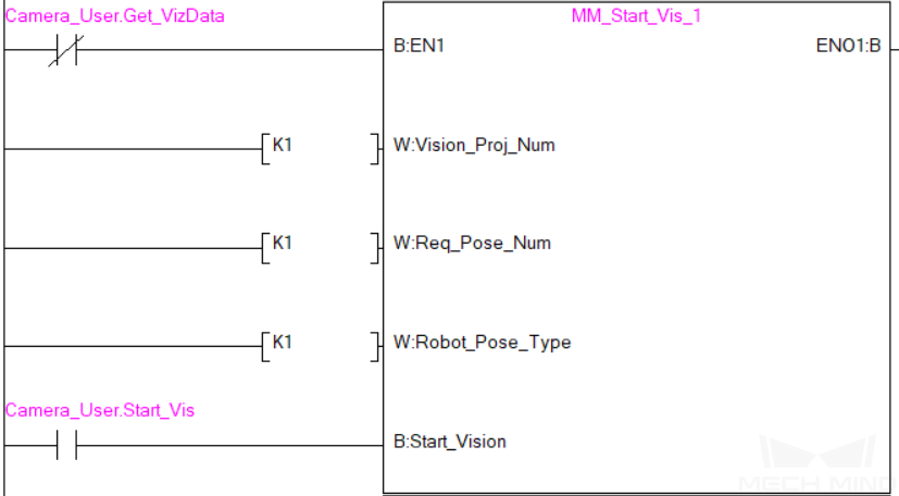
When Camera_User.Start_Vis is at the rising edge, this example runs Mech-Vision project No. 1, asks the project to send over 1 vision point, and the PLC will send the current joint positions and flange pose of the robot to Mech-Vision.
Get Vision Target(s)
This command is for applications that use Mech-Vision but not Mech-Viz. It obtains the vision result from the corresponding Mech-Vision project.
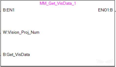
Parameters
Input parameters
Vision_Proj_Num
Mech-Vision Project ID, from 1 to 99.
Get_VisData
Obtain the vision result from the Mech-Vision project at the rising edge.
Returned data MM_Camera global label
Status_Code
1100 is returned if no error occurred.
For other values, please refer to Status Codes and Troubleshooting for the corresponding error.
Status_of_Pose_Sent
1 represents that the waypoint data written in are new.
After the PLC reads the pose data, please run the MM_Empty_Target FB to reset the register to 0.
Number_of_Pose_Sent
Store the number of received vision points, from 1 to 20.
Target_Pose
Store the received waypoint poses as TCPs.
Target_Label
Store the integer labels corresponding to the poses. Labels are set in Mech-Vision.
Example
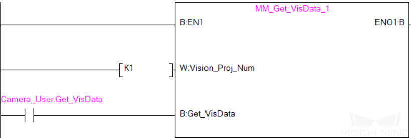
When Camera_User.Get_VisData is at the rising edge, this example obtains the vision result from Mech-Vision project No. 1.
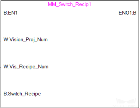
Switch Mech-Vision Recipe
This command specifies which parameter recipe of the Mech-Vision project to use. For more information on parameter recipe, please see Parameter Recipe.
Note
This command must be executed BEFORE MM_Start_Vis.
The corresponding Mech-Vision project must have parameter recipes already configured and saved.
Parameters
Input parameters
Vision_Proj_Num
Mech-Vision Project ID, from 1 to 99.
Vision_Recipe_Num
The ID of a parameter recipe in the Mech-Vision project, from 1 to 99.
Switch_Recipe
Switch the parameter recipe at the rising edge.
Returned data from the MM_Camera global label
Status_Code
1107 is returned if no error occurred.
For other values, please refer to Status Codes and Troubleshooting for the corresponding error.
Example
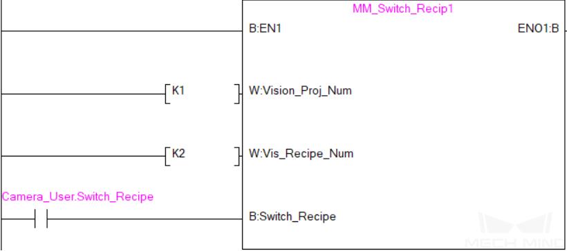
When Camera_User.Switch_Recipe is at the rising edge, this example switches the parameter recipe used to No. 2 in Mech-Vision project No. 1.
Get Result of Step “Path Planning” in Mech-Vision
This command is for applications that use Mech-Vision but not Mech-Viz. It obtains the collision-free path planned by the “Path Planning” Step from the corresponding Mech-Vision project.
Note
MM_Start_Vis must be executed before this command.
The Port Type parameter of the “Procedure Out” Step in the Mech-Vision project must be set to “Predefined (robot path)”.
Before executing this command, please set Req_Pose_Num in MM_Start_Vis to 0 to reduce the times of execution of this command. If Req_Pose_Num in MM_Start_Vis is set to 1, then every time this command is executed, only 1 waypoint is returned, and this command must be executed multiple times to obtain all the waypoints.

Parameters
Input parameters
Vision_Proj_Num
Mech-Vision Project ID, from 1 to 99.
Request_Pose_Type
Whether Mech-Vision should send waypoin poses as joint positions or TCPs, 1 or 2.
1: Mech-Vision sends joint positions 2: Mech-Vision sends TCPs
Get_VisData
Obtains the planned path from Mech-Vision at the rising edge.
Attention
The Request_Pose_Type here and the Robot_Pose_Type in the MM_Start_Vis and MM_Start_Viz FBs all correspond to the same Pose Type label in the MM_Camera global label. Therefore, if these parameters are set to different values, the programming should ensure that the two values do not take effect at the same time.
Returned data from the MM_Camera global label
Status_Code
1103 is returned if no error occurred.
For other values, please refer to Status Codes and Troubleshooting for the corresponding error.
Status_of_Pose_Sent
1 represents that the waypoint data written in are new.
After the PLC reads the pose data, please run the MM_Empty_Target FB to reset the register to 0.
Number_of_Pose_Sent
Store the number of received waypoints, from 1 to 20.
Index_of_Vision_Picking_Point
Store the position of the Vision Move waypoint in the path.
Example path: Move_1, Move_2, Vision Move_3, Move_3 In this path, the position of the Vision Move waypoint is 3. If the path does not contain Vision Move waypoint, the return value is 0.
Target_Pose
Store the received waypoint poses.
Target_Label
Store the integer labels corresponding to the poses. Labels are set in Mech-Vision.
Speed_Percentage
Store the velocity settings corresponding to the poses.
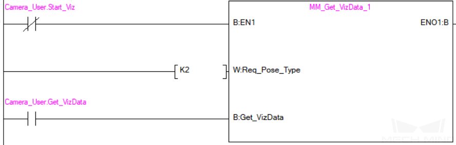
Example

When Camera_User.Get_VizData is at the rising edge, this example obtains the planned path from Mech-Vision in the form of joint positions.
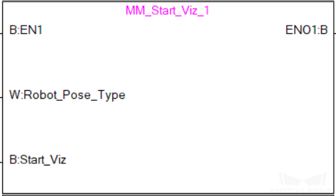
Start Mech-Viz Project
This command is for applications that use both Mech-Vision and Mech-Viz. It runs the corresponding Mech-Viz project (which triggers the corresponding Mech-Vision project to run), and sets the initial joint positions of the simulated robot in Mech-Viz.
Parameters
Input parameters
Robot_Pose_Type
Set the initial pose for the simulated robot in Mech-Viz, from 0 to 2
See the following table for explanations of the 3 values
Label Camera_User.Robot_Pose_JPS
The joint positions received from the robot
Data type: one-dimensional array [0..5] of Real
Label Camera_User.Robot_Pose_Flange
The flange pose received from the robot
Data type: one-dimensional array [0..5] of Real
Start_Viz
Start the Mech-Viz project at the rising edge.
The following table explains the relationship between Robot_Pose_Type and Camera_User. Robot_Pose_JPS/Camera_User. Robot_Pose_Flange.
Robot_Pose_Type
Camera_User. Robot_Pose_JPS
Camera_User. Robot_Pose_Flange
Description
Applicable scenario
0
0, 0, 0, 0, 0, 0
0, 0, 0, 0, 0, 0
No need to input robot pose to Mech-Viz. The simulated robot in Mech-Viz moves from JPs = [0, 0, 0, 0, 0, 0] to the first waypoint.
Project is in the eye-to-hand mode. This setting is not recommended.
1
Current JPs of the robot
Current flange pose of the robot
Robot JPs and flange pose must be input to Mech-Viz. The simulated robot in Mech-Viz moves from the input JPs to the first waypoint.
This setting is recommended for projects in the eye-in-hand mode.
2
Specific JPs of the robot
0, 0, 0, 0, 0, 0
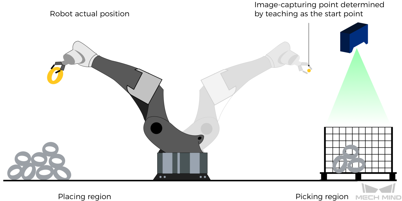
The robot JPs of a point determined by teaching must be input to Mech-Viz. The input JPs are used to trigger Mech-Viz to plan the next path in advance while the robot is not in the camera capture region, as shown below. The simulated robot in Mech-Viz moves from the input JPs to the first waypoint.
This setting is recommended for projects in the eye-to-hand mode.
The reason for setting robot pose type to 2 when the project is in the eye-to-hand mode:
In the eye-to-hand mode, the camera can perform image capturing for the next round of path planning before the robot returns to the camera capture region and picking region, shortening the cycle time.
If robot pose type is set to 1, the robot’s current pose is sent to Mech-Viz. The simulated robot will move from the input pose to the first waypoint in the planned path, while the real robot might move to another point first, and then move to the first waypoint. Therefore, the path of the real robot may contain unpredicted collisions, leading to safety hazards.
In conclusion, robot pose type should be set to 2 for projects in the eye-to-hand mode.
Returned data from the MM_Camera global label
Status_Code
2103 is returned if no error occurred.
For other values, please refer to Status Codes and Troubleshooting for the corresponding error.
Example
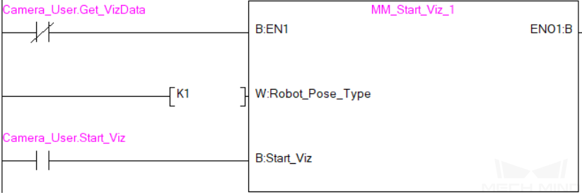
When Camera_User.Start_Viz is at the rising edge, this example runs the corresponding Mech-Viz project, and sets the initial joint positions of the simulated robot to the current joint positions of the real robot.
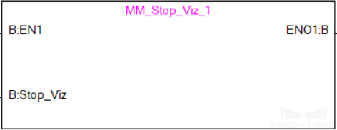
Stop Mech-Viz Project
This command stops the execution of the Mech-Viz Project. This command is only needed if the Mech-Viz project falls into an infinite loop or cannot be stopped normally.
Parameters
Input parameters
Stop_Viz
Stop the execution of the Mech-Viz project at the rising edge.
Returned data from the MM_Camera global label
Status_Code
2104 is returned if no error occurred.
For other values, please refer to Status Codes and Troubleshooting for the corresponding error.
Example
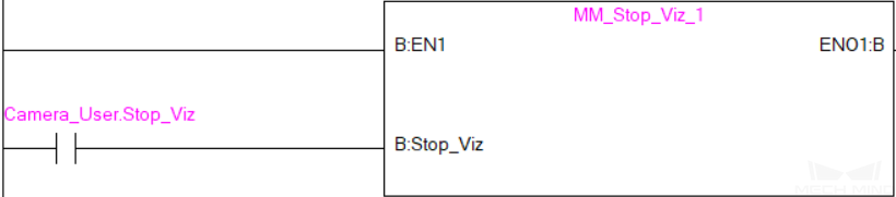
When Camera_User.Stop_Viz is at the rising edge, this example stops the execution of the Mech-Viz project.
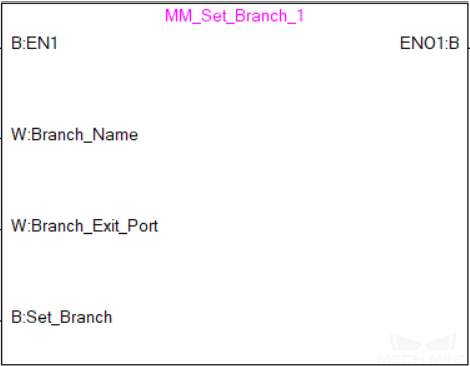
Select Mech-Viz Branch
This command is used to select along which branch the Mech-Viz project should proceed. Such branching is achieved by adding Branch by Msg Step(s) to the project. This command specifies which exit port such Step(s) should take.
Note
MM_Start_Viz must be executed BEFORE this command.
When the next Step to be executed in Mech-Viz is a Branch by Msg Step, Mech-Viz will wait for this command to send the exit port number it should take.
Parameters
Input parameters
Branch_Name
Step ID of the Branch by Msg Step, from 1 to 99.
Branch_Exit_Port
The number of the exit port to take, from 1 to 99.
Add 1 to the port number displayed in Mech-Viz. E.g., value 1 corresponds to exit port 0 in Mech-Viz.
Set_Branch
Sets the branch to take at the rising edge.
Returned data from the MM_Camera global label
Status_Code
2105 is returned if no error occurred.
For other values, please refer to Status Codes and Troubleshooting for the corresponding error.
Example
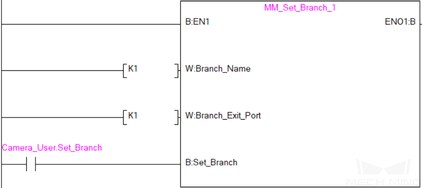
When Camera_User.Set_Branch is at the rising edge, this example tells Mech-Viz to take exit port 1 for the Branch by Msg Step whose Step ID is 1.
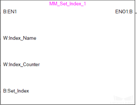
Set Move Index
This command sets the value for the Current Index parameter of Mech-Viz Steps. Steps that have this parameter include Move by List, Move by Grid, Custom Pallet Pattern, and Smart Pallet Pattern.
Note
MM_Start_Viz must be executed BEFORE this command.
Parameters
Input parameters
Index_Name
Step ID of the Step with the index parameter. The Step ID can be read in the Step’s parameters.
Index_Counter
The index value that should be set the next time this Step is executed.
When this command is sent, the current index value in Mech-Viz will become the parameter value minus 1.
When the Mech-Viz project runs to the Step specified by this command, the current index value in Mech-Viz will be increased by 1 to become the parameter’s value.
Set_Index
The trigger signal to set the index. The rising edge does the trigger.
Returned data from the MM_Camera global label
Status_Code
2106 is returned if no error occurred.
For other values, please refer to Status Codes and Troubleshooting for the corresponding error.
Example
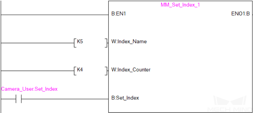
When Camera_User.Set_Index is at the rising edge, this example sets the Current Index value to 3 for the Step whose Step ID is 5. When the Step is executed, the Current Index value will be added 1 and become 4.
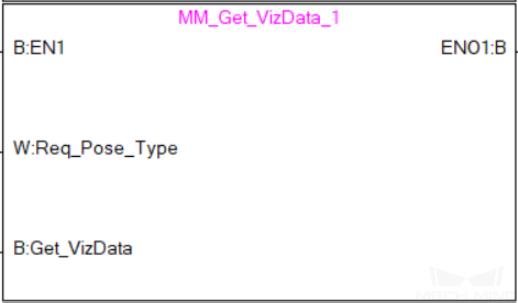
Get Planned Path
This command obtains the planned path from Mech-Viz.
Parameters
Input parameters
Request_Pose_Type
Whether Mech-Viz should send waypoint poses as joint positions or TCPs, 1 or 2.
1: Mech-Viz sends joint positions 2: Mech-Viz sends TCPs
Get_VizData
Obtains the planned path from Mech-Viz at the rising edge.
Attention
The Request_Pose_Type here and the Robot_Pose_Type in the MM_Start_Vis and MM_Start_Viz FBs all correspond to the same Pose Type label in the MM_Camera global label. Therefore, if these parameters are set to different values, the programming should ensure that the two values do not take effect at the same time.
Returned data from the MM_Camera global label
Status_Code
2100 is returned if no error occurred.
For other values, please refer to Status Codes and Troubleshooting for the corresponding error.
Status_of_Pose_Sent
1 represents that the waypoint data written in are new.
After the PLC reads the pose data, please run the MM_Empty_Target FB to reset the register to 0.
Number_of_Pose_Sent
Store the number of received waypoints, from 1 to 20.
Index_of_Vision_Picking_Point
Store the position of the Vision Move waypoint in the path.
Example path: Move_1, Move_2, Vision Move_3, Move_3 In this path, the position of the Vision Move waypoint is 3. If the path does not contain Vision Move waypoint, the return value is 0.
Target_Pose
Store the received waypoint poses.
Target_Label
Store the integer labels corresponding to the poses. Labels are set in Mech-Vision.
Speed_Percentage
Store the velocity settings corresponding to the poses.
Example
When Camera_User.Get_VizData is at the rising edge, this example obtains the planned path from Mech-Viz in the form of TCPs.
Get DO List
This command obtains the planned DO signal list for controlling multiple sections of a sectioned vacuum gripper.
Note
MM_Get_VizData must be executed BEFORE this command.
Please configure the Mech-Viz project based on the template project in xxx\Mech-Mind Software Suite-x.x.x\Mech-Center\tool\viz_project\suction_zone, and set the suction cup configuration file in the Mech-Viz project.
Parameters
Input parameters
Get_DoList
Obtains the planned DO signal list from Mech-Viz at the rising edge.
Returned data from the MM_Camera global label
Status_Code
2102 is returned if no error occurred.
For other values, please refer to Status Codes and Troubleshooting for the corresponding error.
DO_LIST
The list of 64 DO values, in the range of 0 to 999, with -1 being the placeholder value.
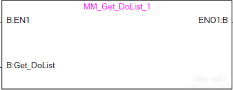
Example
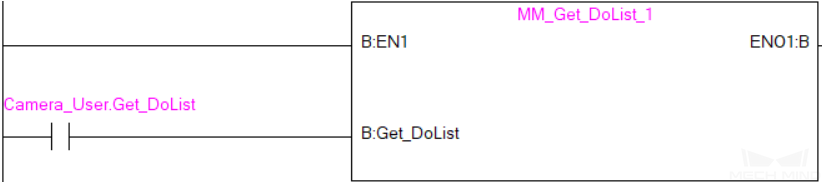
When Camera_User.Get_DoList is at the rising edge, this example obtains the planned DO signal list from Mech-Viz and stores it in the DO_LIST label.
Input Object Dimensions to Mech-Vision
This command inputs object dimensions to the Mech-Vision project.
Note
This command must be executed BEFORE MM_Start_Vis.
The corresponding Mech-Vision project must contain the “Read Object Dimensions” Step, and the Read Sizes from Properties parameter of this step must be checked.
Parameters
Input parameters
Vision_Proj_Num
Mech-Vision Project ID, from 1 to 99.
Label Camera_User.External_Input_Box_Dimension
The 3D dimensions (in mm) to be input to the Mech-Vision project, as an array of 3 real numbers.
Set_Box_Dimension
Input the object dimensions to the Read Object Dimensions Step in the Mech-Vision project at the rising edge.
Returned data from the MM_Camera global label
Status_Code
1108 is returned if no error occurred.
For other values, please refer to Status Codes and Troubleshooting for the corresponding error.
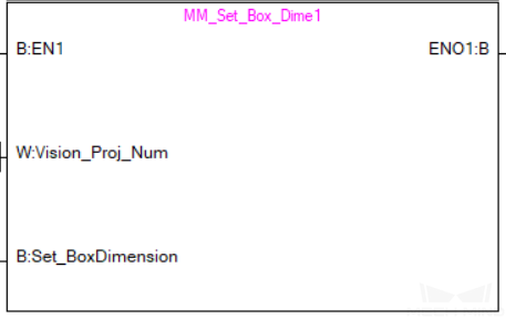
Example
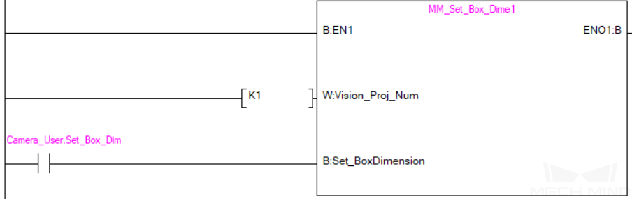
When Camera_User.Set_Box_Dimension is at the rising edge, this example sets the object dimensions in the Read Object Dimensions Step in the Mech-Vision project No. 1 to the values in External_Input_Box_Dimension.
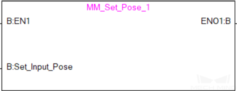
Input TCP to Mech-Viz
This command inputs TCP data to the External Move Step.
Note
This command must be executed BEFORE MM_Start_Viz.
Please configure the Mech-Viz project based on the template project in xxx\Mech-Mind Software Suite-x.x.x\Mech-Center\tool\viz_project\outer_move, and put the External Move Step at a proper position in the workflow.
Parameters
Input parameters
Label Camera_User.External_Input_Pose
The TCP data to be input to Mech-Viz (in mm), as an array of 6 real numbers.
Set_Input_Pose
Input the TCP data to the External Move Step in the Mech-Viz project at the rising edge.
Returned data from the MM_Camera global label
Status_Code
2107 is returned if no error occurred.
For other values, please refer to Status Codes and Troubleshooting for the corresponding error.
Example
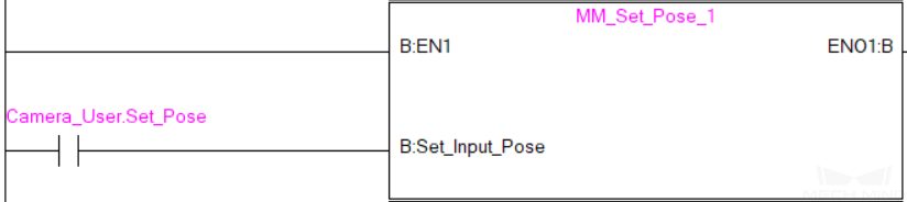
When Camera_User.Set_Pose is at the rising edge, this example sends the TCP data stored in External_Input_Pose to the External Move Step in the Mech-Viz project.
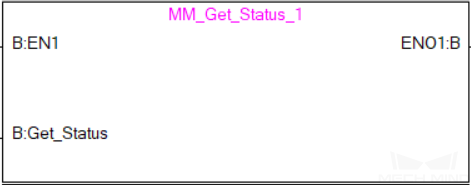
Get Software Status
This command is currently capable of checking whether Mech-Vision is ready to run projects. In the future, this command can be used for obtaining the execution status of Mech-Vision, Mech-Viz, and Mech-Center.
Parameters
Input parameters
Get_Status
Check whether Mech-Vision is ready to run projects at the rising edge.
Returned data from the MM_Camera global label
Status code
Software status. 1101 means the Mech-Vision project is ready to run. Other codes mean the project is not ready.
Example
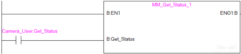
When Camera_User.Get_Status is at the rising edge, this example checks the status code and stores it in the Status_Code label.
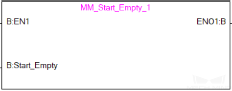
Clear Target Data
This command clears the obtained data stored in the Target_Pose, Target_Label, and Speed_Percentage.
Parameters
Input parameters
Start_Empty
Clear the data stored in Target_Pose, Target_Label, and Speed_Percentage when value set to 1.
Returned data from the MM_Camera global label
Status_Code
3103 is returned if no error occurred.
For other values, please refer to Status Codes and Troubleshooting for the corresponding error.
Target_Pose
Obtained waypoint poses.
Target_Label
Obtained labels.
Speed_Percentage
Obtained velocity settings.
Example
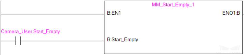
When the value of Camera_User.Start_Empty is set to 1, the data stored in the Target_Pose, Target_Label, and Speed_Percentage are cleared.
Description of the Status Codes
Please refer to Status Codes and Troubleshooting for detailed information.