Mitsubishi MC - MELSEC-Q Series PLC Commands
Start Mech-Vision Project
In scenarios where only Mech-Vision is used, this command starts the Mech-Vision project that executes image capturing and performs vision recognition.
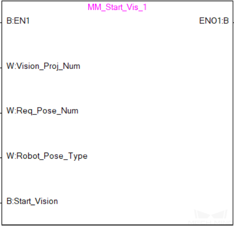
Input Parameters
Vision_Proj_Num: Mech-Vision project ID, which is the number before the project name in the Project List panel in Mech-Vision. Please ensure that the project has been set to autoloaded, or else the project ID will not be displayed.
Req_Pose_Num: The number of vision points that Mech-Vision is requested to send, from 0 to 20, where 0 indicates “send all”.
Robot_Pose_Type: The type of pose of the real robot to input to Mech-Vision. The value range is 0–3.
Camera_User.Robot_Pose_JPS: Current joint positions of the robot. The data type is one-dimensional Array [0..5] of Real.
Camera_User.Robot_Pose_Flange: Current flange pose of the robot. The data type is one-dimensional Array [0..5] of Real.
The following table explains the relationship between Robot_Pose_Type and Camera_User.Robot_Pose_JPS/Camera_User.Robot_Pose_Flange.
Robot_Pose_Type
Camera_User. Robot_Pose_JPS
Camera_User. Robot_Pose_Flange
Description
Applicable scenario
0
0, 0, 0, 0, 0, 0
0, 0, 0, 0, 0, 0
No need to input robot pose to Mech-Vision.
Project is in the eye-to-hand mode. If the “Path Planning” Step is used, the planned path starts at the Home point set in the path planning tool.
1
Current joint positions of the robot
Current flange pose of the robot
Robot joint positions and flange pose must be input to Mech-Vision.
Project is in the eye-in-hand mode. Applicable to most robots (excluding truss robots).
2
0, 0, 0, 0, 0, 0
Current flange pose of the robot
Robot flange pose must be input to Mech-Vision.
Project is in the eye-in-hand mode. The robot has no joint positions and only flange pose (such as truss robots).
3
Joint positions of the start point of the planned path
0, 0, 0, 0, 0, 0
The joint positions of the path start point must be input to Mech-Vision.
Project is in the eye-to-hand mode and the Mech-Vision project contains the “Path Planning” Step, whose start point needs to be set from the robot side.
Start_Vision: Trigger the start of the Mech-Vision project at the rising edge.
Returned data from the MM_Camera global label
Status_Code: If there is no error, status code 1102 will be returned. Otherwise, the corresponding error code will be returned.
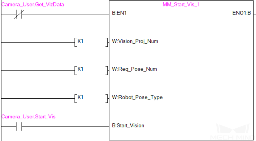
Example
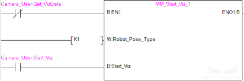
When there is a rising edge on the label Camera_User.Start_Vis, the PLC runs Mech-Vision project No. 1, asks the project to send over 1 vision point, and send the current joint positions and flange pose of the robot to Mech-Vision.
Get Vision Target(s)
This command is called after Start Mech-Vision Project to obtain the vision points output by Mech-Vision and transform the vision points into vision targets.
The transformation process, in which the pose of the vision point is transformed into the robot TCP, is as follows:
Rotate the poses around their Y axes by 180 degrees.
Determine whether the definition of the reference frame used by the robot model involves robot base height, and add a vertical offset accordingly.
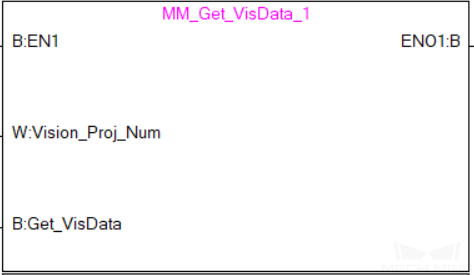
Input parameters
Vision_Proj_Num: Mech-Vision project ID, which is the number before the project name in the Project List panel in Mech-Vision. Please ensure that the project has been set to autoloaded, or else the project ID will not be displayed.
Get_VisData: The signal to request the result from the Mech-Vision project at the rising edge.
Returned data from the MM_Camera global label
Status_Code: If there is no error, status code 1100 will be returned. Otherwise, the corresponding error code will be returned.
Status_of_Pose_Sent: 1 represents that the returned data is new and can be read. After the PLC reads the data, please run the MM_Empty_Target FB to reset the register to 0.
Number_of_Pose_Sent: The number of vision targets obtained, from 0 to 20.
Target_Pose: The pose of the vision targets.
Target_Label: The pose of the vision targets.
Example
When there is a rising edge on the label Camera_User.Get_VisData, vision targets of Mech-Vision project No. 1 will be obtained.

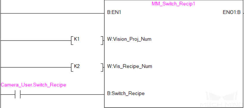
Switch Mech-Vision Recipe
This command switches the parameter recipe used by the Mech-Vision project. It should be executed before Start Mech-Vision Project.
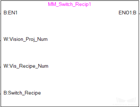
Input parameters
Vision_Proj_Num: Mech-Vision project ID, which is the number before the project name in the Project List panel in Mech-Vision. Please ensure that the project has been set to autoloaded, or else the project ID will not be displayed.
Vision_Recipe_Num: The ID number of the parameter recipe to switch to in Mech-Vision.
Switch_Recipe: The signal to switch the parameter recipe in the Mech-Vision project at the rising edge.
Returned data from the MM_Camera global label
Status_Code: If there is no error, status code 1107 will be returned. Otherwise, the corresponding error code will be returned.
Example
When there is a rising edge on the label Camera_User.Switch_Recipe, the recipe will be switched to No. 2 in Mech-Vision project No. 1.
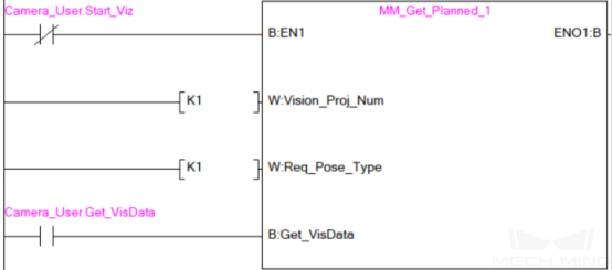
Get Result of Step “Path Planning” in Mech-Vision
After executing Start Mech-Vision Project, this command gets the collision-free planned path output by the “Path Planning” Step in Mech-Vision.
When using this command, the Port Type parameter of the “Procedure Out” Step must be set to “Predefined (robot path)”.
Hint
Before executing this command, please set Req_Pose_Num in Start Mech-Vision Project to 0 to reduce the times of execution of this command. If Req_Pose_Num in Start Mech-Vision Project is set to 1, then every time this command is executed, only 1 waypoint can be returned, and this command must be executed multiple times to obtain all the waypoints.
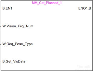
Input parameters
Vision_Proj_Num: Mech-Vision project ID, which is the number before the project name in the Project List panel in Mech-Vision. Please ensure that the project has been set to autoloaded, or else the project ID will not be displayed.
Request_Pose_Type: The type of waypoint pose returned by the “Path Planning” Step.
1: The waypoint poses are returned in the form of JPs.2: The waypoint poses are returned in the form of TCP.
Attention
Request_Pose_Type and Robot_Pose_Type in the MM_Start_Vis and MM_Start_Viz functions correspond to the same Pose_Type variable in the MM_Camera global label. If the set values are different, they cannot take effect at the same time.
Get_VisData: The signal to request the result from the Mech-Vision project at the rising edge.
Returned data from the MM_Camera global label
Status_Code: If there is no error, status code 1103 will be returned. Otherwise, the corresponding error code will be returned.
Status_of_Pose_Sent: 1 represents that the returned data is new and can be read. After the PLC reads the data, please run the MM_Empty_Target FB to reset the register to 0.
Number_of_Pose_Sent: The number of waypoints from the “Path Planning” Step, from 1 to 20.
Index_of_Vision_Picking_Point: The position of the Vision Move Step in the entire robot motion path. For example, if the path is composed of Steps Fixed-Point Move_1, Fixed-Point Move_2, Vision Move, Fixed-Point Move_3 sequentially, the position of Vision Move is 3.
Target_Pose: The waypoint poses in TCP. The type is determined by Request_Pose_Type.
Target_Label: The integer labels assigned to the waypoints.
Speed_Percentage: The velocities set in the path planning tool.
Example
When there is a rising edge on the label Camera_User.Get_VisData, the path planned by the Mech-Vision project will be obtained in the form of joint positions.
Start Mech-Viz Project
In scenarios where both Mech-Vision and Mech-Viz are used, this command starts the Mech-Viz project that triggers the corresponding Mech-Vision project, and therefore the Mech-Viz project can plan the robot path based on the vision points received from Mech-Vision.
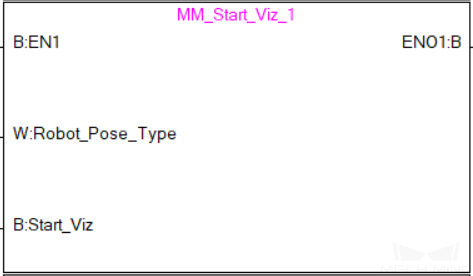
Input parameters
Robot_Pose_Type: The type of pose of the real robot to input to Mech-Viz. The value range is from 0 to 2.
Camera_User.Robot_Pose_JPS: Current joint positions of the robot. The data type is one-dimensional Array [0..5] of Real.
Camera_User.Robot_Pose_Flange: Current flange pose of the robot. The data type is one-dimensional Array [0..5] of Real.
The following table explains the relationship between Robot_Pose_Type and Camera_User.Robot_Pose_JPS/Camera_User.Robot_Pose_Flange.
Robot_Pose_Type
Camera_User. Robot_Pose_JPS
Camera_User. Robot_Pose_Flange
Description
Applicable scenario
0
0, 0, 0, 0, 0, 0
0, 0, 0, 0, 0, 0
No need to input robot pose to Mech-Viz. The simulated robot in Mech-Viz moves from JPs = [0, 0, 0, 0, 0, 0] to the first waypoint.
Project is in the eye-to-hand mode. This setting is not recommended.
1
Current JPs of the robot
Current flange pose of the robot
Robot JPs and flange pose must be input to Mech-Viz. The simulated robot in Mech-Viz moves from the input JPs to the first waypoint.
This setting is recommended for projects in the eye-in-hand mode.
2
Specific JPs of the robot
0, 0, 0, 0, 0, 0
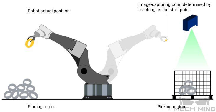
The robot JPs of a point determined by teaching must be input to Mech-Viz. The input JPs are used to trigger Mech-Viz to plan the next path in advance while the robot is not in the camera capture region, as shown below. The simulated robot in Mech-Viz moves from the input JPs to the first waypoint.
This setting is recommended for projects in the eye-to-hand mode.
The reason for setting Robot_Pose_Type to 2 when the project is in the eye-to-hand mode:
In the eye-to-hand mode, the camera can perform image capturing for the next round of path planning before the robot returns to the camera capture region and picking region, shortening the cycle time.
If Robot_Pose_Type is set to 1, the robot’s current pose is sent to Mech-Viz. The simulated robot will move from the input pose to the first waypoint in the planned path, while the real robot might move to another point first, and then move to the first waypoint. Therefore, the path of the real robot may contain unpredicted collisions, leading to safety hazards.
In conclusion, Robot_Pose_Type should be set to 2 for projects in the eye-to-hand mode.
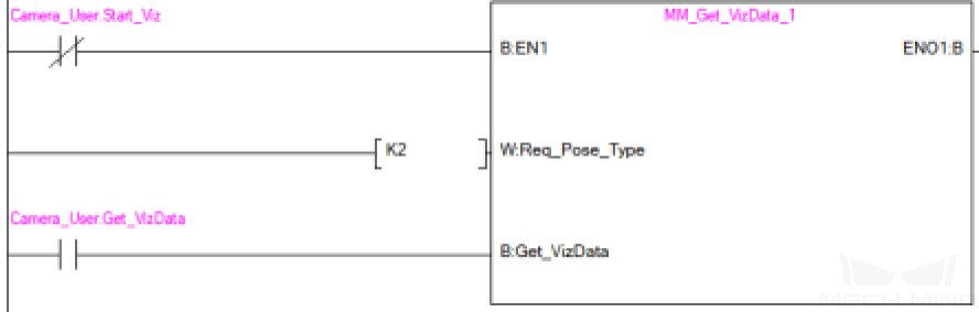
Start_Vision: Trigger Mech-Viz project to run at the rising edge.
Returned data from the MM_Camera global label
Status_Code: If there is no error, status code 2103 will be returned. Otherwise, the corresponding error code will be returned.
Example
When there is a rising edge on the label Camera_User.Start_Viz, Mech-Viz project will be started, and the current joint positions and flange pose of the robot are sent to Mech-Vision.
Stop Mech-Viz Project
This command stops the Mech-Viz project. This command is needed only when the Mech-Viz project falls into an infinite loop or cannot be stopped normally.
Input parameters
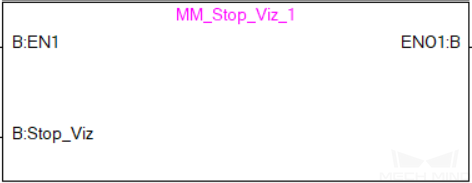
Stop_Viz: Stop Mech-Viz project at the rising edge.
Returned data from the MM_Camera global label
Status_Code: If there is no error, status code 2104 will be returned. Otherwise, the corresponding error code will be returned.
Example
When there is a rising edge on the label Camera_User.Stop_Viz, the Mech-Viz project will be stopped.

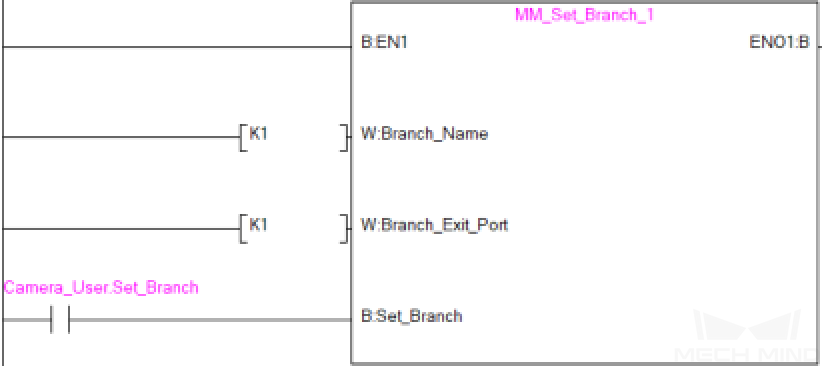
Select Mech-Viz Branch
This command is used to select along which branch the Mech-Viz project should proceed. Such branching is achieved by adding Branch by Msg Step(s) to the project. This command specifies which exit port such Step(s) should take. Start Mech-Viz Project must be called BEFORE this command.
Input parameters
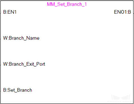
Branch_Name: The Step ID (integer) of the Branch by Msg Step.
Branch_Exit_Port: This parameter is used for specifying which exit port of the specified Step, i.e., the branch, the project should run along. The value should be an integer ([1, N]).
Hint
An exit port number is the 1-based index of the specified exit port on the Step. For example, if the specified exit port is the second exit port of the Step from left to right, the exit port number is 2.
Set_Branch: Specify the port which Branch by Msg Step should take.
Returned data from the MM_Camera global label
Status_Code: If there is no error, status code 2105 will be returned. Otherwise, the corresponding error code will be returned.
Example
When there is a rising edge on the parameter Camera_User.Set_Branch, Mech-Viz will take exit port 1 for the Branch by Msg Step whose Step ID is 1.
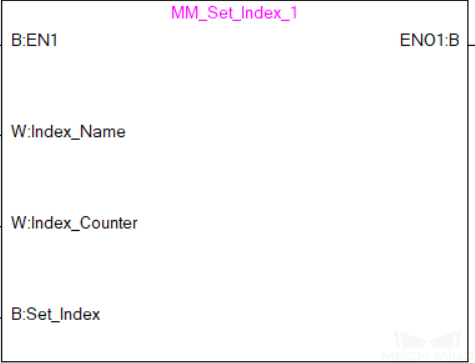
Set Move Index
This command is for setting the index parameter of a Step that involves sequential or separate motions or operations. Steps with index parameters include Move by List, Move by Grid, Custom Pallet Pattern, Smart Pallet Pattern, etc.
Start Mech-Viz Project must be called BEFORE this command.
Input parameters
Index_Name: The ID of the Step with the Index parameters.
Index_Counter: The index value that should be set the next time this Step is executed. When this command is sent, the current index value in Mech-Viz will become the parameter value minus 1. When the Mech-Viz project runs to the task specified by this command, the current index value in Mech-Viz will be increased by 1 to become the parameter’s value.
Returned data from the MM_Camera global label
Status_Code: If there is no error, status code 2106 will be returned. Otherwise, the corresponding error code will be returned.
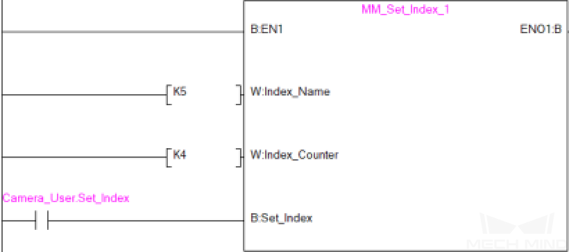
Example
When there is a rising edge on the parameter Camera_User.Set_Index, the Current Index value for the Step whose Step ID is 5 will be set to 4. When the Step is executed, the Current Index value will be added 1 and become 5.
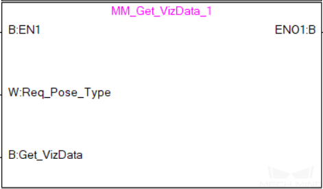
Get Planned Path
This command obtains the planned path from Mech-Viz.
Input parameters
Request_Pose_Type: Specify the type of waypoint pose.
1: The waypoint poses returned should be in JPs.2: The waypoint poses returned should be in TCP.
Attention
Request_Pose_Type and Robot_Pose_Type in the MM_Start_Vis and MM_Start_Viz functions correspond to the same Pose_Type variable in the MM_Camera global label. If the set values are different, they cannot take effect at the same time.
Get_VisData: The signal to request the result from the Mech-Viz project at the rising edge.
Returned data from the MM_Camera global label
Status_Code: If there is no error, status code 2100 will be returned. Otherwise, the corresponding error code will be returned.
Status_of_Pose_Sent: 1 represents that the returned data is new and can be read. After the PLC reads the data, please run the MM_Empty_Target FB to reset the register to 0.
Number_of_Pose_Sent: The number of waypoints output from Mech-Viz, from 0 to 20.
Index_of_Vision_Picking_Point: The position of the Vision Move Step in the entire robot motion path. For example, if the path is composed of Steps Fixed-Point Move_1, Fixed-Point Move_2, Vision Move, Fixed-Point Move_3 sequentially, the position of Vision Move is 3.
Target_Pose: The waypoint pose. The type is determined by Request_Pose_Type.
Target_Label: The integer labels assigned to the waypoints.
Speed_Percentage: The velocity in percentage set in move-type Step parameters.
Example
When there is a rising edge on the parameter Camera_User.Get_VizData, waypoints in TCP of Mech-Viz project will be obtained.
Get DO List
This command gets the planned DO signal list, which is used to control multiple grippers or multiple suction cup sections. Before executing this command, Get Planned Path needs to be executed to obtain the planned motion path from Mech-Viz.
Please deploy the Mech-Viz project based on the template project in suction_zone under the folder where Mech-Mind Software Suite is installed (Mech-Center/tool/viz_project).
In the parameters of the Set DO List Step:
Select “Standard Interface” under “Receiver”
Select “Get DO List from ‘Vision Move’
Select a Vision Move Step that needs the DO signal list in the drop-down list of the “Select ‘Vision Move’” parameter
Input parameters
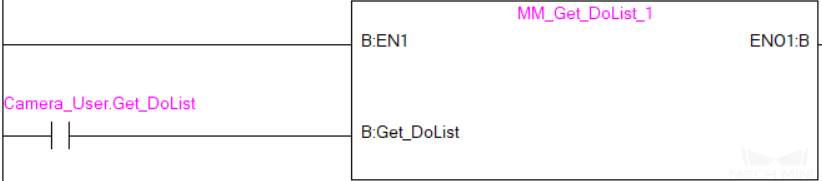
Get_DoList: Obtain the planned DO Signal list at the rising edge.
Returned data from the MM_Camera global label
Status_Code: If there is no error, status code 2102 will be returned. Otherwise, the corresponding error code will be returned.
DO_LIST: Returns 64 DO port numbers from Mech-Viz.
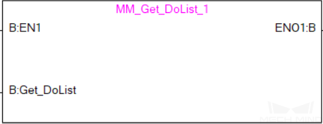
Example
When there is a rising edge on the parameter Camera_User.Get_DoList, the DO signal list planned by Mech-Viz will be stored in DO array.
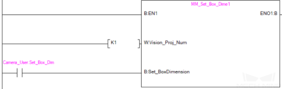
Input Object Dimensions to Mech-Vision
This command is used for dynamically inputting object dimensions into the Mech-Vision project. Please confirm the actual object dimensions before running the Mech-Vision project.
The Mech-Vision project should contain the Read Object Dimensions Step, and the Step’s parameter Read Sizes from Properties should be selected.
Input parameters
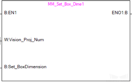
Vision_Proj_Num: Mech-Vision project ID, which is the number before the project name in the Project List panel in Mech-Vision. Please ensure that the project has been set to autoloaded, or else the project ID will not be displayed.
Camera_User.External_Input_Box_Dimension: Input the object’s length, width, and height (in mm) to the Mech-Vision project.
Set_Box_Dimension: Input the object dimensions in the Mech-Vision project at the rising edge.
Returned data from the MM_Camera global label
Status_Code: If there is no error, status code 1108 will be returned. Otherwise, the corresponding error code will be returned.
Example
When there is a rising edge on the label Camera_User.Set_Box_Dimension, the object dimensions in the Read Object Dimensions Step will be set as the values assigned in External_Input_Box_Dimension[0–2].
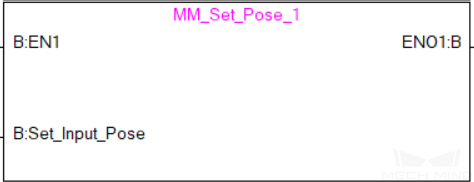
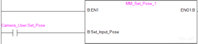
Input TCP to Mech-Viz
This command is used for dynamically inputting robot TCP into the Mech-Viz project after Start Mech-Viz Project is executed. The Step that receives the robot TCP is External Move.
Please deploy the Mech-Viz project based on the template project in tool/viz_project/outer_move under the folder where Mech-Mind Software Suite is installed, and add the External Move Step to a proper position in the workflow.
Input parameters
Camera_User.External_Input_Pose: TCP of the robot in mm.
Set_Input_Pose: Input the TCP to Mech-Viz at the rising edge.
Returned data from the MM_Camera global label
Status_Code: If there is no error, status code 2107 will be returned. Otherwise, the corresponding error code will be returned.
Example
When there is a rising edge on the label Camera_User.Set_Pose, the TCP data stored in External_Input_Pose[0–5] will be sent to the External Move Step in the Mech-Viz project.
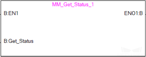
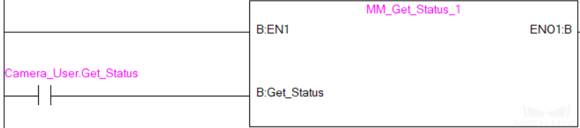
Get Software Status
This command is designed for checking the software running status of Mech-Vision, Mech-Viz, and Mech-Center. At present, this command only supports checking whether Mech-Vision is ready for running the project.
Input parameters
Get_Status: Check whether Mech-Vision is ready to run projects at the rising edge.
Returned data from the MM_Camera global label
Status_Code: 1101 indicates the Mech-Vision project is ready to run, while other codes indicate that the project is not ready.
Example
When there is a rising edge on the label Camera_User.Get_Status, the system status code will be returned and stored in the MM_Camera.Status_Code.
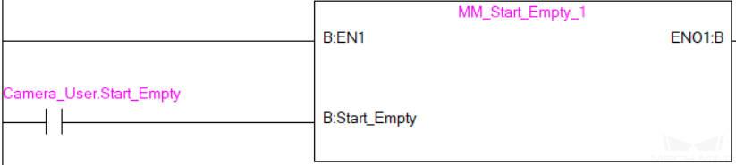
Clear Target Data
This command is for clearing the obtained data in variables Target_Pose, Target_Label, and Speed_Percentage.
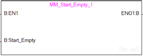
Input parameters
Start_Empty: The trigger signal for clearing the obtained data in variables Target_Pose, Target_Label, and Speed_Percentage at the rising edge.
Returned data from the MM_Camera global label
Target_Pose: Obtained pose data.
Target_Label: Obtained label data.
Speed_Percentage: Obtained velocity data.
Example
When there is a rising edge on the label Camera_User.Start_Empty, the obtained data in variables Target_Pose, Target_Label, and Speed_Percentage will be cleared.
Appendix
Description of the Status Codes
Please refer to Status Codes and Troubleshooting for detailed information.