Communication Configuration and Example Program Usage
This topic provides instructions on setting up the Standard Interface communication based on the EtherNet/IP protocol between an Allen‑Bradley PLC (hereafter referred to as AB PLC) and Mech-Mind Software Suite.
Hardware and Software Requirements
Hardware
AB PLC: A 1769-L19ER-BB1B module PLC is used as an example in the following instructions.
Power adapter: AC 220 V to DC 24 V
IPC: IPC with HMS IXXAT INpact 40 PCIe interface card installed
Network switch and Ethernet cables
Network switch and Ethernet cables

Software
Software |
Description |
Installed Location |
AB PLC Studio 5000 |
AB PLC programming software |
Computer that is used for AB PLC programming |
PCIe Card and Driver Software |
IPC |
|
Mech-Mind Software Suite 1.7.2 or above |
Mech-Mind Software Suite |
IPC |
Used for setting up the IP address of the PCIe card |
IPC |
Please copy and paste the following files to a PC with Studio 5000 installed.
EDS file: 005A002B003A0100.EDS, which is used to provide the identity information of the IPC in the EtherNet/IP network.
The EDS file is stored in the folder where Mech-Mind Software Suite is installed:
Mech-Center/Robot_Interface/EthernetIP.PLC example program files:
CameraSignalsMove.L5X: used to transfer the vision system signals
CameraTest.L5X: used to test the vision system
MM EtherNet IP Interface Program.L5X: used to implement the functions of various interface commands
The example program files are stored in the folder where Mech-Mind Software Suite is installed:
Mech-Center/Robot_Interface/EthernetIP/Programming Samples/AB PLC EthernetIP.
Configure IPC and Initiate Communication
Check PCIe Card and Driver Software
Please make sure that the INpact EIP Slave PCIe interface card has been pressed into the PCIe slot of the IPC.
Start the IPC, go to , and check if the driver software VCI4 INpact PCIe has been installed.

Set up “Robot and Interface Configuration” in Mech-Vision
Click Robot and Interface Configuration on the toolbar of Mech-Vision.
Select Listed robot from the Select robot drop-down menu, and then click Select robot model.
Select the robot model that you use, and then click Next.
Select the following options and click Apply.
Interface Type: Standard Interface
Protocol: ETHERNET IP
Make sure the Interface Service is started: on the toolbar of Mech-Vision, the Interface Service switch on the far right is flipped and turned to blue.
Configure IP address of the PCIe Card
Use an Ethernet cable to connect the network ports of the IPC and the IXXAT INpact 40 PCIe interface card.
Attention
After configuring the IP and initiating communication successfully, the Ethernet cable used here can be removed.
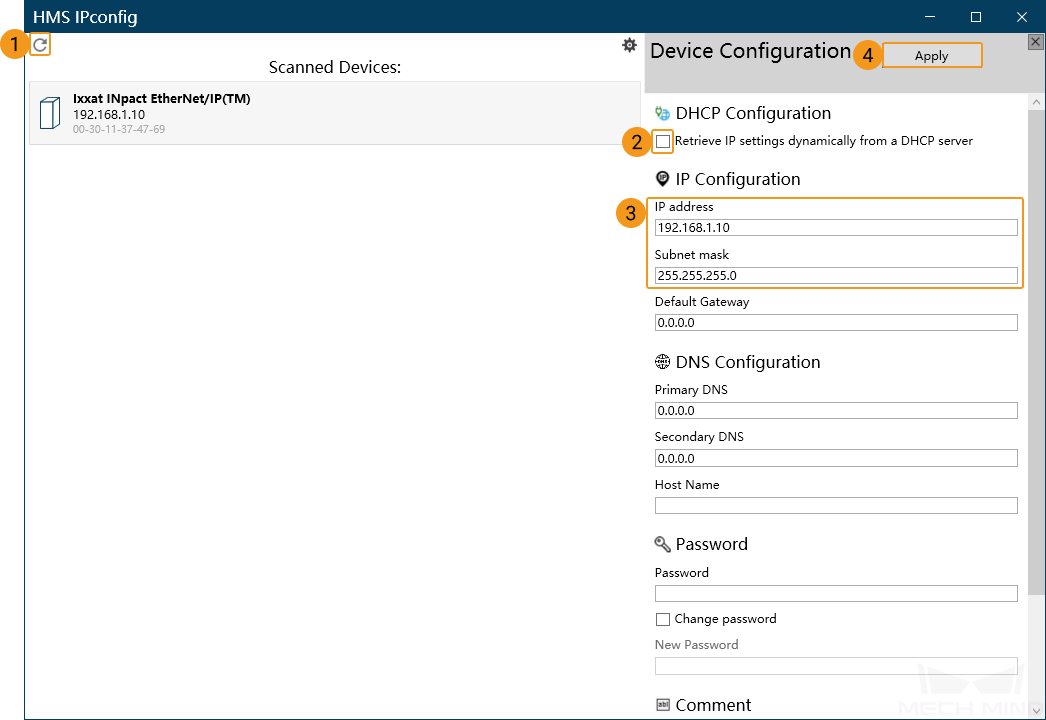
Open HMS IPconfig, click the scan icon and unselect “Retrieve IP settings dynamically from a DHCP server”, and then enter the IP address and subnet mask. After configuration, click Apply and exit the software.
Create and Configure the PLC Project
Create the PLC Project
On the computer, open Studio 5000 software, click New Project, and a New Project window will pop up.

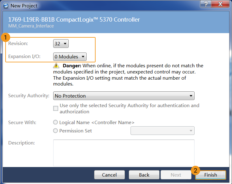
Click Logix, and select the corresponding CPU series and model according to the AB PLC used (a 1769-L19ER-BB1B module PLC is used as an example in the following instructions). Enter the project Name, select the Location, and click Next.

Select Revision and Expansion I/O according to the actual situation, and click Finish to enter the project interface.
Set the IP Address of PLC
On the computer, go to , and a Select Network Interface window will pop up.

Select the driver for the Ethernet adapter connected to the PLC and click OK.

In the BootP DHCP EtherNet/IP Commissioning Tool window, go to .

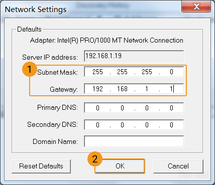
Set the subnet mask and gateway and click OK.
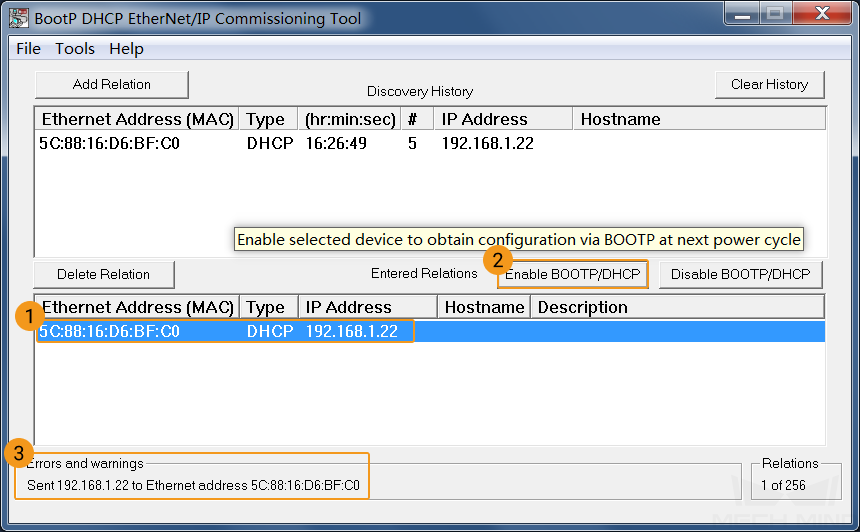
Click Add Relation, enter the MAC address and IP address of PLC in the pop-up window (the figure below shows the address used in the example), and click OK.

Select the created Relation, click Enable BOOTP/DHCP to enable the BOOTP function. If successful, the message “Sent 192.168.1.22 to Ethernet address 5C:88:16:D6:BF:C0” will be displayed in the status bar below. If unsuccessful, please check the network connection and IP setting.
Select the created Relation, click Disable BOOTP/DHCP to disable the BOOTP function. If successful, the message “[Disable BOOTP/DHCP] Command successful” will be displayed first in the status bar below, and then “Unable to service DHCP request from 5C:88:16:D6:BF:C0” will be displayed. Then you can close the BootP DHCP EtherNet/IP Commissioning Tool window.

If unsuccessful, please check your network connection and IP settings.
Connect the Controller
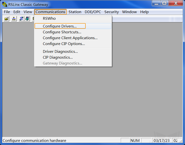
On the computer, go to , and a RSLinx Classic Gateway window will pop up.

In the menu bar, go to .
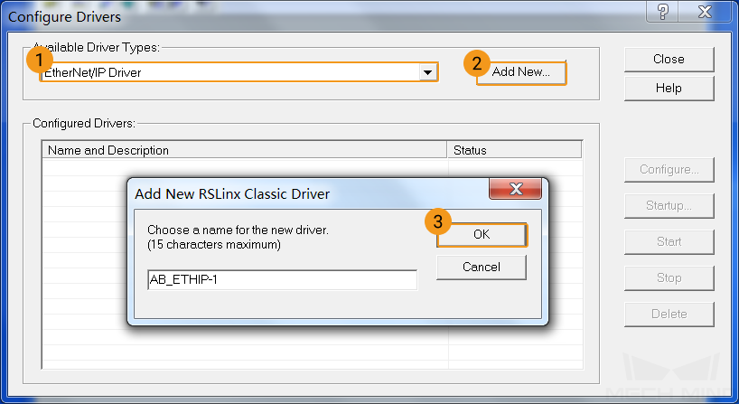
In the Configure Drivers window, please follow the steps below.
Select EtherNet/IP Driver in the drop-down menu from Available Driver Types and click Add New.
In the pop-up Add New RSLinx Classic Driver window, you can use the default name and then click OK.
In the pop-up Configure driver: AB_ETHIP-1 window, select the local subnet of PLC, and click OK.

Go back to the Configure Drivers window, click Close.

In the Controller Organizer panel of Studio 5000, go to , click the specific CPU module, and click the RSWho icon on the toolbar.

In the Who Active (RSLinx Classic) window, expand the AB_ETHIP-1 by clicking the plus (+) sign next to it, select the specific CPU module to be connected, and click Set Project Path in the lower right corner to set the path.
It is set successfully if the path changes from <none> to AB_ETHIP-1\192.168.1.22 and then click Close.

Install EDS File and Configure Communication
In the Studio 5000 interface, go to .
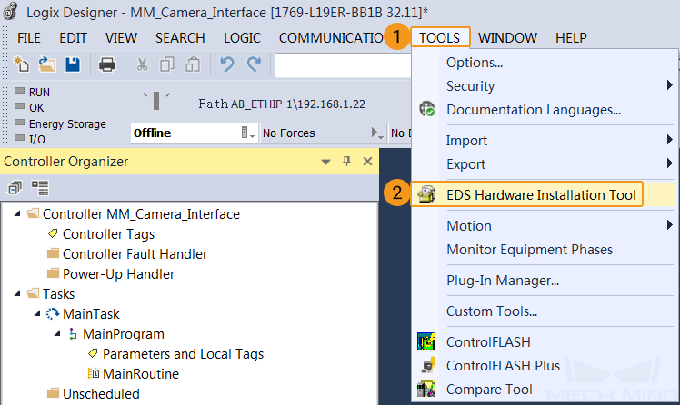
In Rockwell Automation’s EDS Wizard window, please follow the steps below.
Click Next.

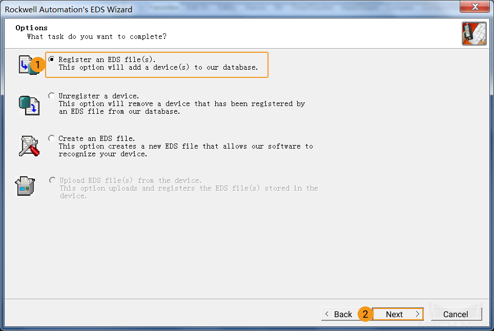
Select Register an EDS file(s) and then click Next.
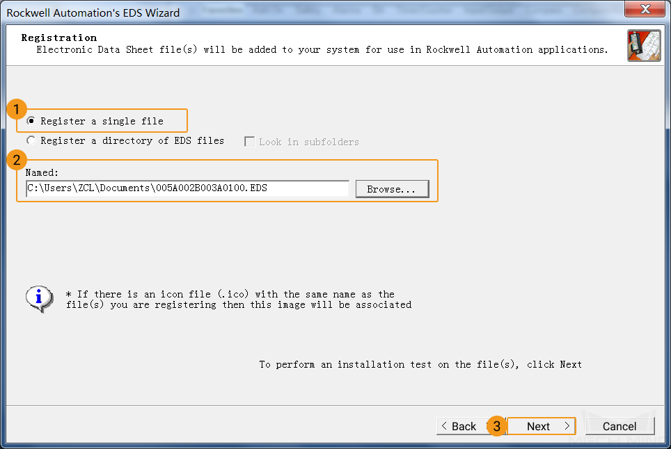
Select Register a single file then click Browse. Select the corresponding EDS file (copied from the IPC in advance) and then select Next.
Click Next.

Select Next to accept the default icon.

Select Next.

Click Finish if the message in the figure below appears.

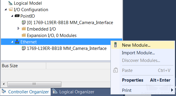
In the Controller Organizer panel, go to , right-click the Ethernet, and click New Module.
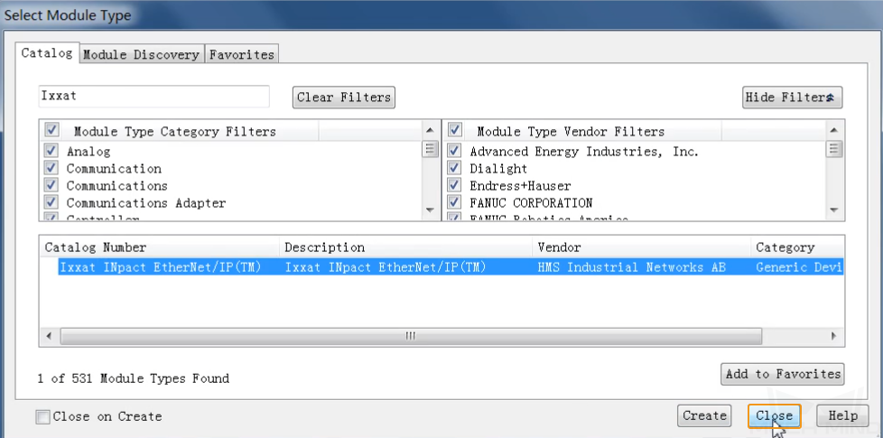
In the Select Module Type window, type Ixxat in the search bar, select Ixxat INpact EtherNet/IP(TM), and click Create.

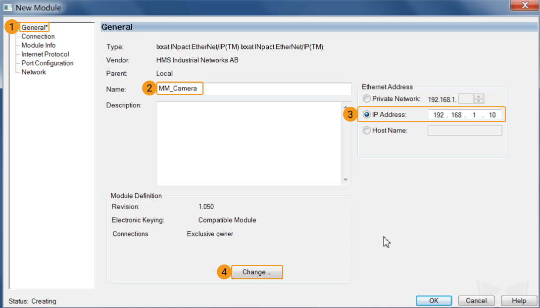
In the New Module window, click the General tab and enter the name MM_Camera (the name cannot be changed as it needs to be consistent with the example name). Set the IP address of the vision system slave device. The IP address set in this example is 192.168.1.10, which should be the same as the IP address set in HMS IPConfig. Click Change.
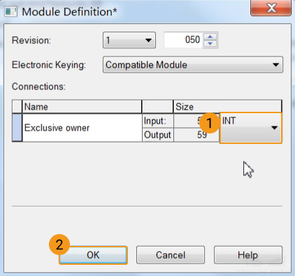
A window will pop up as shown below, modify the Size type as INT, and click OK.
Click Yes if the message shown below appears.

Go back to the New Module window, click OK.
All the steps are completed, and the device Ixxat INpact EtherNet/IP(TM) MM_Camera has been successfully added to the Ethernet as shown below. In the Select Module Type window, click close.
Import Example Program and Download to PLC
Import Example Programs
Attention
Before you add the example program to a project already in use, it is recommended to import it to a new project and test it first.
In the menu bar of Studio 5000, go to .
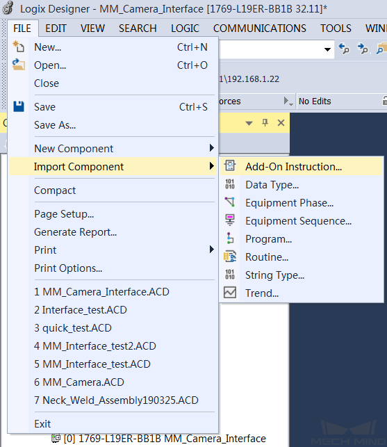
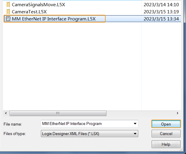
In the pop-up Import Add-On Instruction window, select the example program MM EtherNet IP Interface Program.L5X (which should be copied from the IPC in advance), and click Open.
Click OK in the pop-up window as shown below.

In the menu bar, go to .
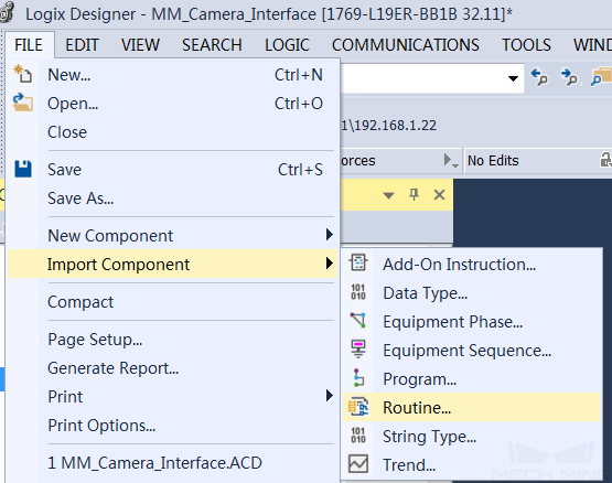
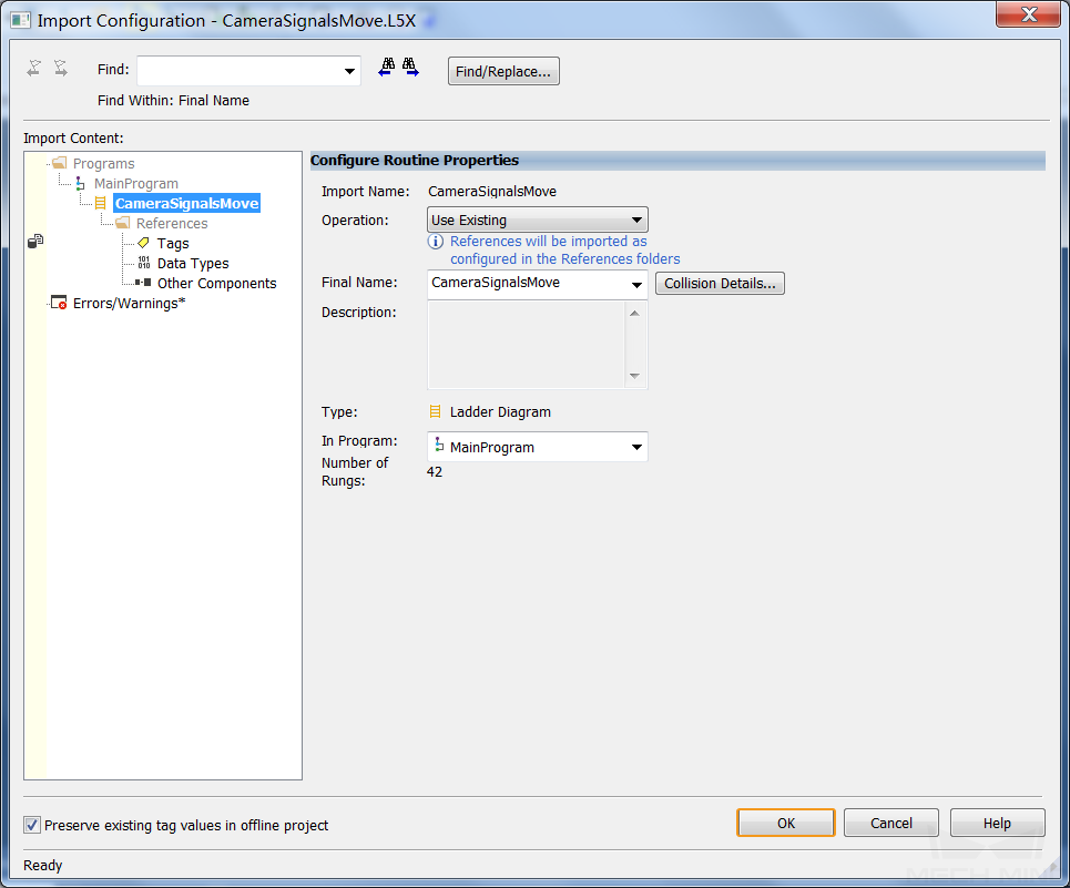
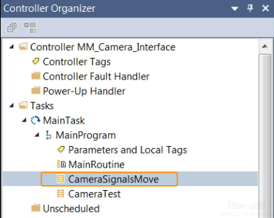
In the pop-up Import Routine window, select CameraSignalsMove.L5X file (which should be copied from the IPC in advance), and click Open.

Click OK in the pop-up window as shown below.
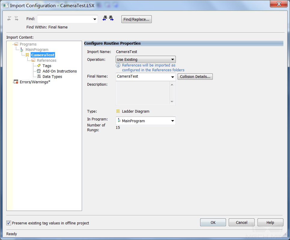
Follow the previous step and import the CameraTest.L5X file (which should be copied from the IPC in advance) into the project.
Download PLC Program to PLC
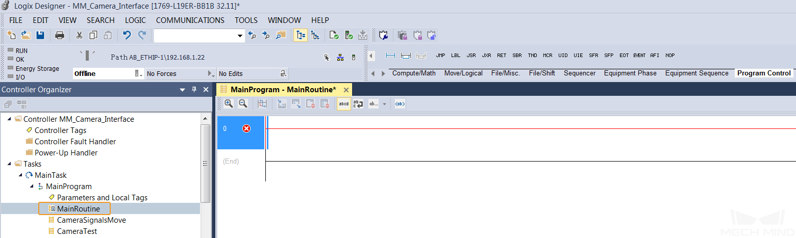
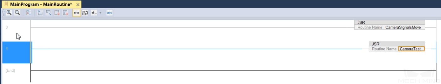
In the Studio 5000 interface, go to , and double-click MainRoutine to open the main program.
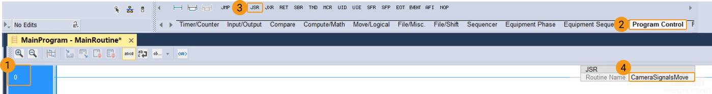
Select Rung 0, go to on the toolbar, and call the CameraSignalsMove program.
Select Rung 0, right-click, and select “Copy Rung” in the context menu. Select Rung End, right-click, and select “Paste” in the context menu to add a new line Rung 1, and change the JSR to CameraTest.
Click the drop-down menu from offline and select Download.

Click Download in the pop-up window as shown below.
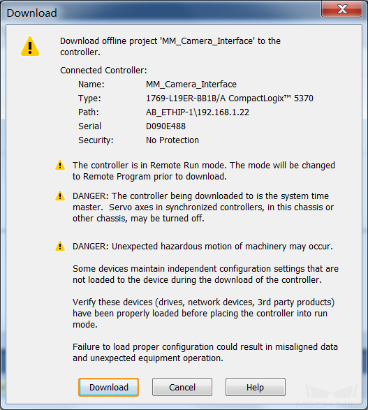
After downloading successfully, an alert message as shown below will pop up. If the system safety can be ensured, select Yes.

The controller is in the Rem Run (remote run) mode.

Check Communication
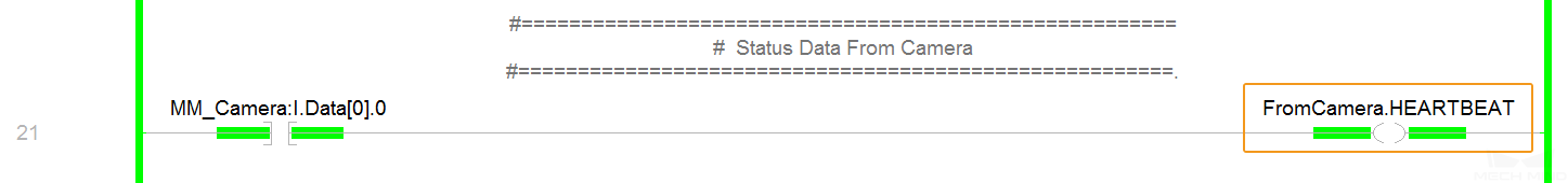
In the Studio 5000 interface, go to , and double-click CameraSignalsMove to open the program.
If the connection is established successfully, the monitor value of FromCamera.HEARTBEAT in Rung 21 will keep changing.
The PLC is successfully connected if the following message is displayed in the Console tab of Mech-Vision Log panel: Connect to ETHERNET IP controller successfully.
If you don’t see this log message, please check if:
The hardware is properly connected;
If the Interface Service has been started successfully in Mech-Vision;
If the PLC program has been successfully downloaded to the PLC.
Test with Vision Projects
This section introduces how to use the example program function block to trigger the Mech-Vision project to obtain vision points and trigger the Mech-Viz project to obtain the planned path.
Prerequisites
Create a Mech-Vision solution. In the project list, right-click the solution and select Autoload Solution. Projects in the solution are also autoloaded and the specific project number will appear in front of the project name.
Create a Mech-Viz project. Right-click the project name in Resources and select Autoload Project.
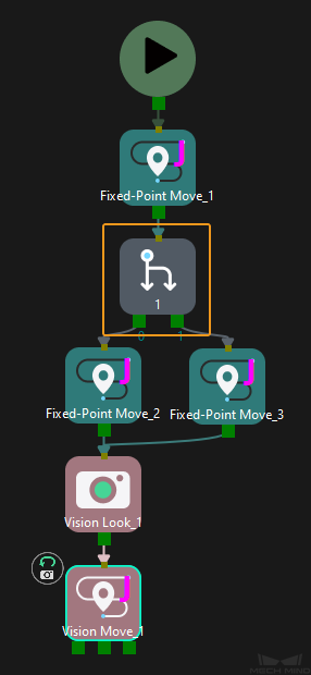
The Mech-Viz project used for testing contains a “Branch by Msg” Step that has been renamed to 1 as shown below.
Run Mech-Vision Project and Obtain Vision Points
Configure Parameters
In the Studio 5000 interface, double-click the program body of CameraTest, and set the status of ToCamera.COM_ENABLE to be always on.

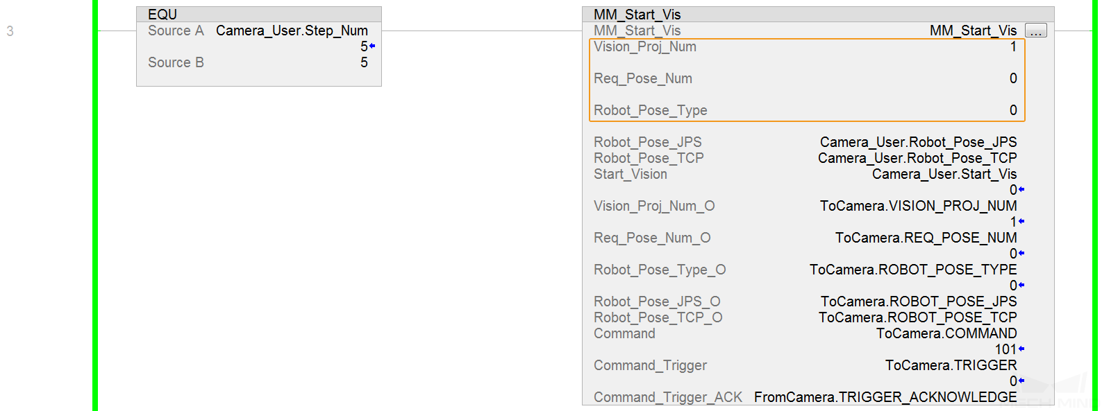
In the Rung 3 of the CameraTest program, set the values as shown below.
Set the value of Vision_Proj_Num to 1, then project No. 1 in Mech-Vision will be started.
Set the value of Req_Pose_Num to 0, which indicates the Mech-Vision project will send all the vision points.
Setting the value of Robot_Pose_Type to 0, which indicates that the project is in eye-to-hand mode, and the image-capturing pose is not needed.
Trigger Mech-Vision Project to Run
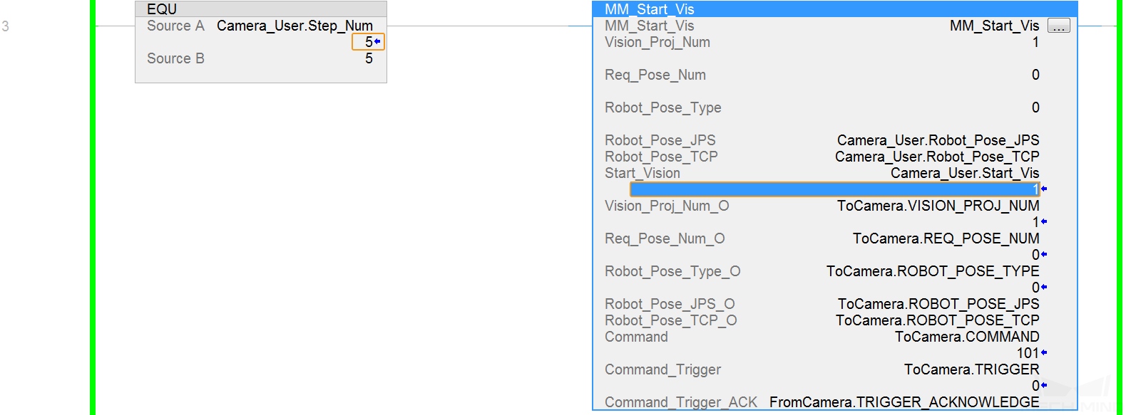
In the Rung 3 of the CameraTest program, set the value of Camera_User.Step_Num to 5. Click the Camera_User.Start_Vis label of MM_Start_Vis and modify the value to 1 to trigger the Mech-Vision project to run. Then reset the value to 0.
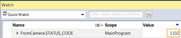
Check whether the returned value of STATUS_CODE is 1102.
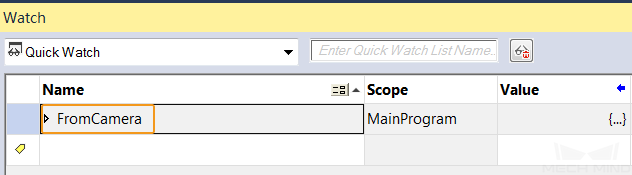
Click the Watch tab in the status bar to open the Watch window, and add the FromCamera label in the Name column.
Expand the levels and check the returned value of STATUS_CODE.
Attention
If the Mech-Vision project is started successfully, the status code 1102 will be returned. Otherwise, the corresponding error code will be returned. Please refer to Status Codes and Troubleshooting for troubleshooting.
Obtain Vision Points from Mech-Vision
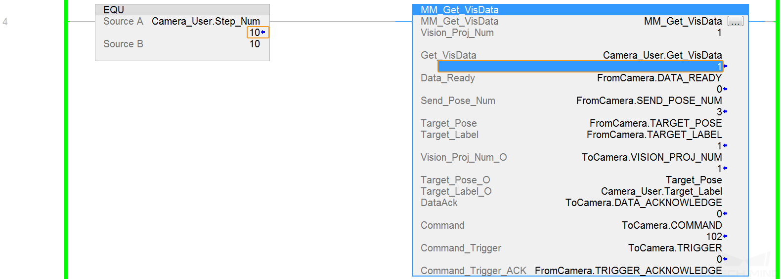
After the STATUS_CODE 1102 is returned, in the Rung 4 of the CameraTest program, modify the value of Camera_User.Step_Num to 10. Click Camera_User.Get_VisData label of MM_Get_VisData and modify the value to 1 to trigger the Mech-Vision project to run. Then reset the value to 0.
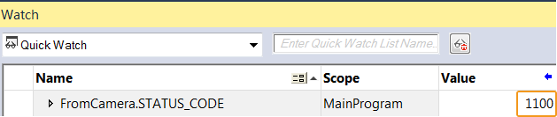
Check the returned value of STATUS_CODE in the Watch window.
Attention
If the vision points are obtained successfully, the status code 1100 will be returned. Otherwise, the corresponding error code will be returned. Please refer to Status Codes and Troubleshooting for troubleshooting.
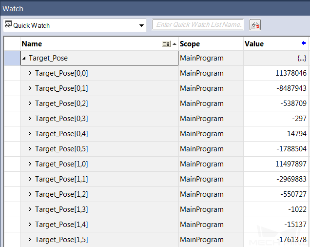
Check the returned value of Target_Pose.
Add the Target_Pose label in the Name column of the Watch window.
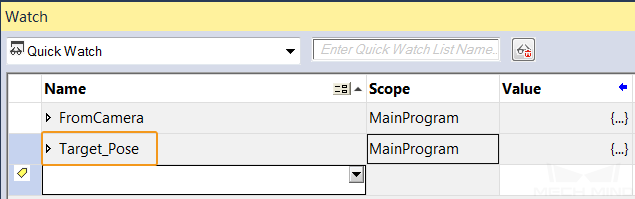
Expand the levels and check the returned values of Target_Pose. The example in the figure below received 2 poses. Divide the transferred values by 10000 to obtain the actual pose data.
Run Mech-Viz Project and Obtain Planned Path
Configure Parameters
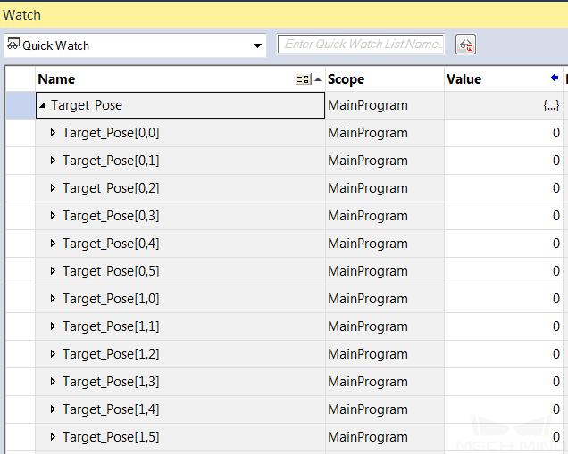
In the Rung 14 of the CameraTest program, set the value of Camera_User.Step_Num to 50. Click the Camera_User.Start_Empty label of MM_Empty_Target and modify the value to 1 to clear the previously obtained vision result. Then reset the value to 0.
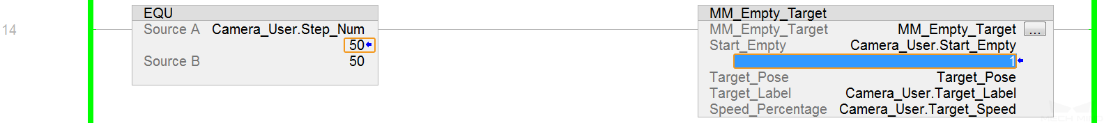
Check the value of Target_Pose after the vision result is cleared in the Watch window.
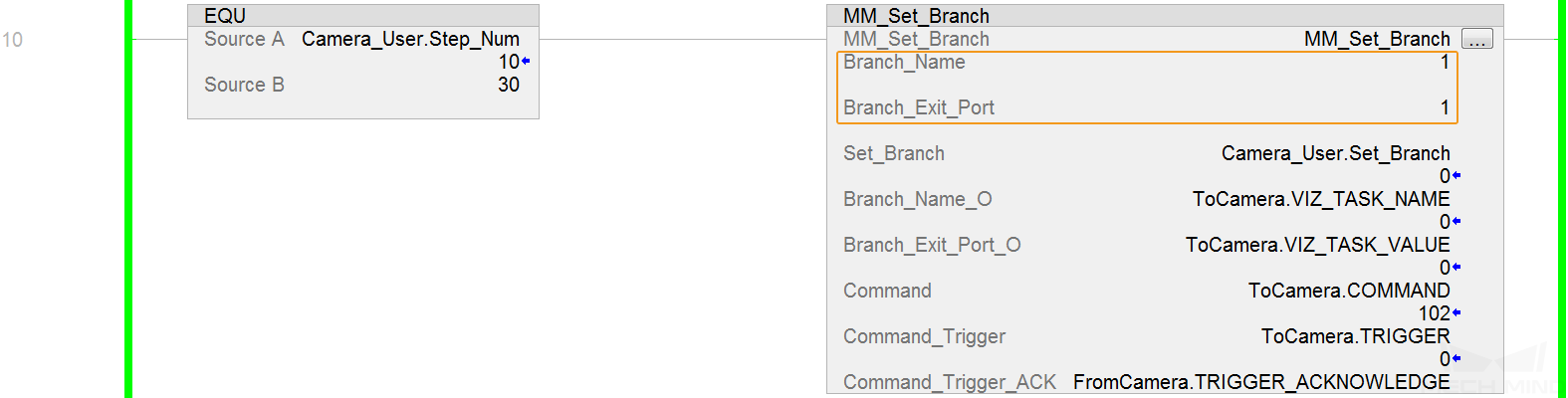
In the Rung 10 of the CameraTest program, set the value of Branch_Name to 1, and the Mech-Viz project will execute along the Branch by Msg Step whose Step ID is 1.
In the Rung 10 of the CameraTest program, set the value of Branch_Exit_Port to 1, and the Mech-Viz project will take exit port 1 for the Branch by Msg Step whose Step ID is 1.
In the Rung 11 of the CameraTest program, set the value of Request_Pose_Type to 1, and Mech-Viz will send data as joint positions.

Trigger Mech-Viz Project to Run
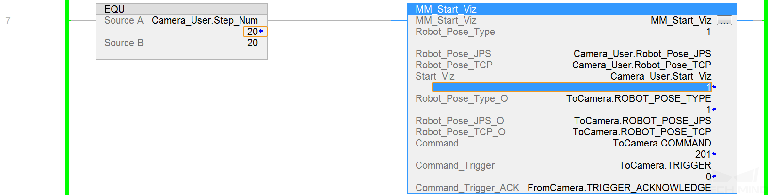
In the Rung 7 of the CameraTest program, set the value of Camera_User.Step_Num to 20. Click the Camera_User.Start_Viz label of MM_Start_Viz and modify the value to 1 to trigger the Mech-Viz project to run. Then reset the value to 0.
Check the returned value of STATUS_CODE in the Watch window.
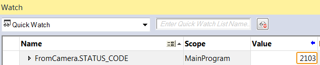
Attention
If the Mech-Viz project is started successfully, the status code 2103 will be returned. Otherwise, the corresponding error code will be returned. Please refer to Status Codes and Troubleshooting for troubleshooting.
Set Branch Exit Port
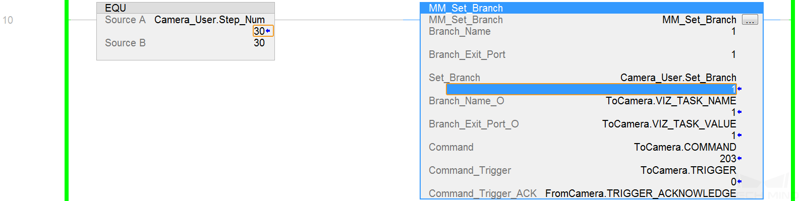
In the Rung 10 of the CameraTest program, set the value of Camera_User.Step_Num to 30. Click the Camera_User.Set_Branch label of MM_Set_Branch and modify the value to 1 to select the exit port of the branch. Then reset the value to 0.
Check the returned value of STATUS_CODE in the Watch window.
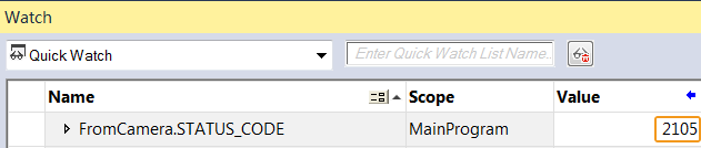
Attention
If the branch is set successfully, the status code 2105 will be returned. Otherwise, the corresponding error code will be returned. Please refer to Status Codes and Troubleshooting for troubleshooting.
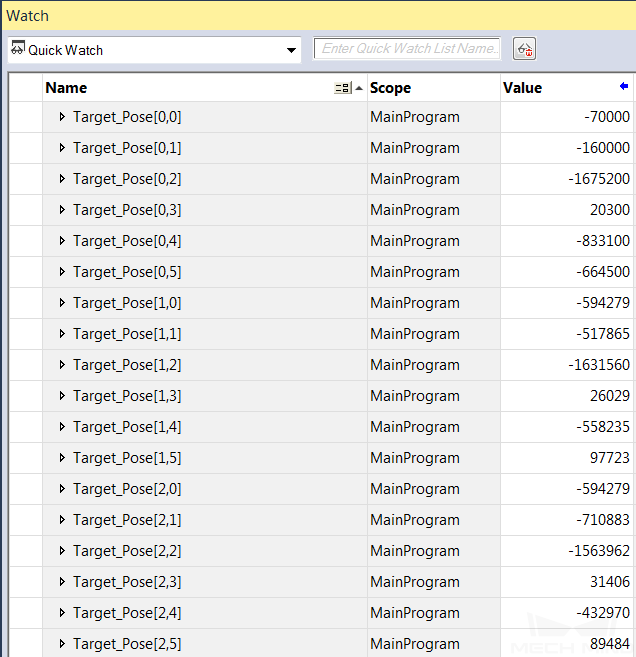
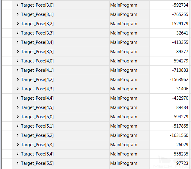
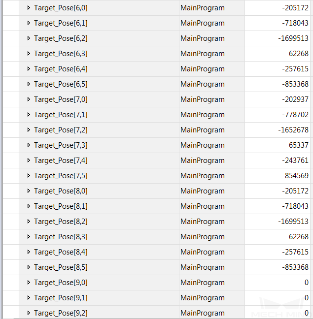
Obtain Planned Path
In the Rung 11 of the CameraTest program, set the value of Camera_User.Step_Num to 35. Click the Camera_User.Get_VizData label of MM_Get_VizData and modify the value to 1 to get the planned path from Mech-Viz. Then reset the value to 0.
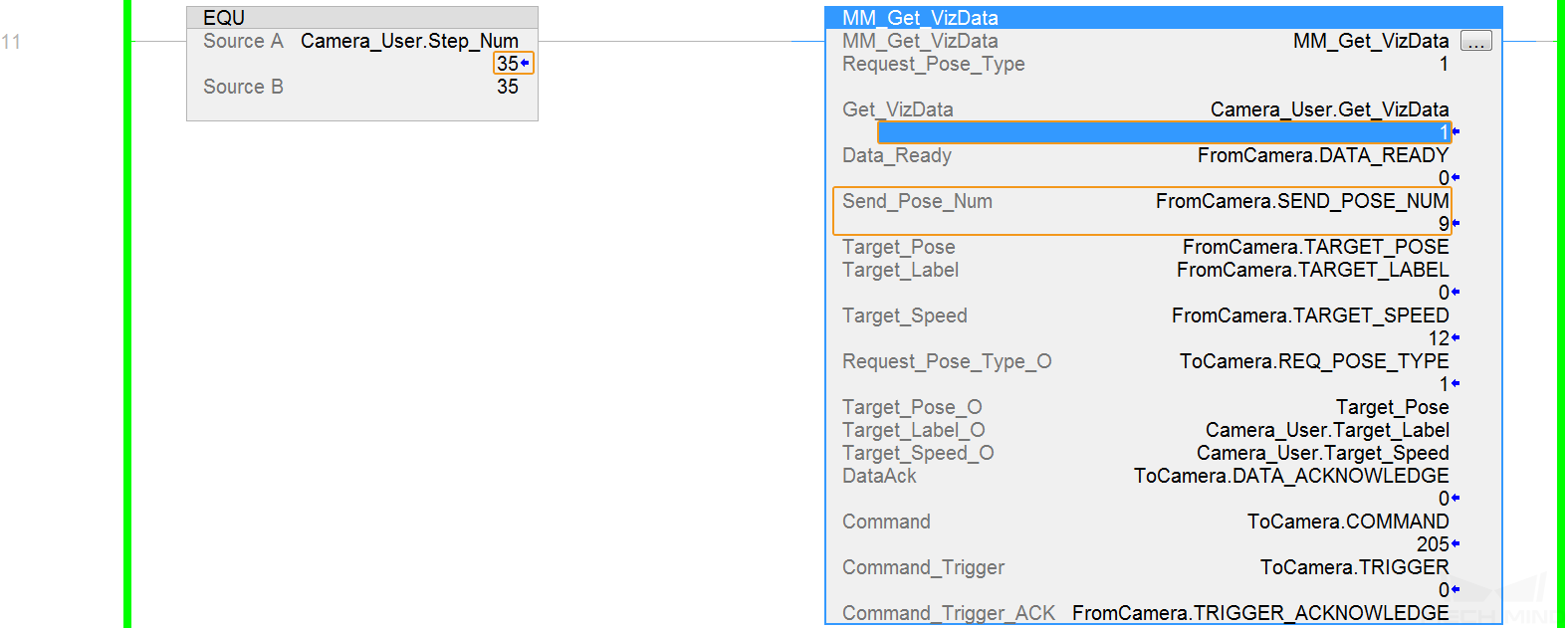
You can see the value of Send_Pose_Num is 9 in the above figure, which indicates that 9 sets of joint positions are obtained in this example program.
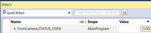
Check the returned values of STATUS_CODE in the Watch window.
Attention
If the planned path is obtained successfully, the status code 2100 will be returned. Otherwise, the corresponding error code will be returned. Please refer to Status Codes and Troubleshooting for troubleshooting.
Check the returned values of Target_Pose in the Watch window. Divide the transferred values by 10000 to obtain the actual pose data.