Commands
This topic introduces the commands for EtherNet/IP communication between a Mitsubishi i-QR Series PLC and Mech-Mind Software Suite.
Start Mech-Vision Project
This command is used for applications that use Mech-Vision but not Mech-Viz. It runs the corresponding Mech-Vision project to acquire and process data.

Parameters
Input parameters
Name |
Description |
Vision_Proj_Num |
Mech-Vision Project ID |
Req_Pose_Num |
Number of vision points for Mech-Vision to send, from 0 to 20, where 0 means “send all” |
Robot_Pose_Type |
Set the robot pose to send to Mech-Vision, from 0 to 3 |
See the following table for explanations of the 4 values |
|
Robot_Pose |
The pose received from the robot, value depends on the value of Robot_Pose_Type |
Data type: two-dimensional array [0..1, 0..5] of DINT, array[0] is joint positions and array[1] is flange pose Before assigning to the array, multiply the floating-point numbers that represent joint positions or the robot flange pose by 10000 to convert the data to 32-bit signed integers. |
|
Start_Vision |
Trigger Mech-Vision project to start when a rising edge occurs |
The following table explains the relationship between Robot_Pose_Type and Robot_Pose.
Robot_Pose_Type value |
Robot_Pose value |
Description |
Applicable scenario |
0 |
0, 0, 0, 0, 0, 0 |
No need to input robot pose to Mech-Vision. |
Project is in the eye-to-hand mode. If the “Path Planning” Step is used, the planned path starts at the Home point set in the path planning tool. |
1 |
Current joint positions and flange pose of the robot |
Robot joint positions and flange pose must be input to Mech-Vision as the image-capturing pose. |
Project is in the eye-in-hand mode. Applicable to most robots (excluding truss robots). |
2 |
Current flange pose of the robot |
Robot flange pose must be input to Mech-Vision as the image-capturing pose. |
Project is in the eye-in-hand mode. The robot has no joint positions and only flange pose (such as truss robots). |
3 |
Joint positions of the start point of the planned path |
The joint positions of the path start point must be input to Mech-Vision. |
Project is in the eye-to-hand mode and the Mech-Vision project contains the “Path Planning” Step, whose start point needs to be set from the robot side. |
System parameter
Name |
Description |
FromCamera.STATUS_CODE |
If the project is started successfully, the status code 1102 will be returned. Otherwise, the corresponding error code will be returned. |
Example

This example starts Mech-Vision project No. 1 when there is a rising edge on the parameter Camera_User.Start_Vision, and asks the project to send over 1 vision point, and the PLC will send the current joint positions and flange pose of the robot to Mech-Vision.
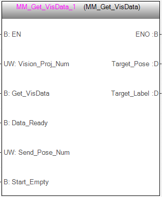
Get Vision Target(s)
This command is for applications that use Mech-Vision but not Mech-Viz. It obtains the vision result from the corresponding Mech-Vision project.
Note
This command can only fetch at most 20 vision targets at a time. Therefore, if Mech-Vision outputs more than 20 vision targets, please execute this command repeatedly until all the vision targets required are obtained.
Parameters
Input parameters
Name |
Description |
Vision_Proj_Num |
Mech-Vision Project ID |
Get_VisData |
Obtain vision points from Mech-Vision project when a rising edge occurs |
Data_Ready |
Indicate that all the pose data is available to read when receiving multiple groups of robot poses |
Send_Pose_Num |
The number of vision points to be sent by Mech-Vision, from 0 to 20 |
Start_Empty |
Clear the obtained data stored in Target_Pose and Target_Label. This parameter will take effect when it is set to 1. |
Output parameters
Name |
Description |
Target_Pose |
The vision pose. The data type is array[0..19, 0..5] of DINT. |
The data from this parameter should be divided by 10000 before using |
|
Target_Label |
The label information of the object recognized by Mech-Vision. The data type is array[0..19] of UDINT. The returned values are integers. |
System parameters
Name |
Description |
FromCamera.STATUS_CODE |
If the vision points are obtained successfully, the status code 1100 will be returned. Otherwise, the corresponding error code will be returned. |
FromCamera.SEND_POSE_TYPE |
The returned value is 2, which suggests that the type of poses obtained via MM_Get_VisData is always in TCP. |
Example

When there is a rising edge on the parameter Camera_User.Get_VisData, vision points of Mech-Vision project No. 1 will be obtained. When Camera_User.Start_Empty is set to 1, data stored in Camera_User.Target_Pose and Camera_User.Target_Label will be cleared.
Switch Mech-Vision Recipe
This command specifies which parameter recipe of the Mech-Vision project to use. For more information on parameter recipe, please see Parameter Recipe.
Note
This command must be called BEFORE MM_Start_Vis.
The corresponding Mech-Vision project must have parameter recipes already configured and saved.

Parameters
Input parameters
Name |
Description |
Vision_Proj_Num |
Mech-Vision Project ID |
Vision_Recipe_Num |
The ID of a parameter recipe in the Mech-Vision project |
Switch_Recipe |
Switch the parameter recipe when a rising edge occurs |
System parameter
Name |
Description |
FromCamera.STATUS_CODE |
If the parameter recipe is switched successfully, the status code 1107 will be returned. Otherwise, the corresponding error code will be returned. |
Example

When there is a rising edge on the parameter Camera_User.Switch_Recipe, the parameter recipe will be switched to No. 2 in Mech-Vision project No. 1.
Get Result of Step “Path Planning” in Mech-Vision
This command is for applications that use Mech-Vision but not Mech-Viz. It obtains the collision-free path planned by the “Path Planning” Step from the corresponding Mech-Vision project.
Note
MM_Start_Vis must be executed before this command.
The Port Type parameter of the “Procedure Out” Step in the Mech-Vision project must be set to “Predefined (robot path)”.
Before executing this command, please set Req_Pose_Num in MM_Start_Vis to 0 to reduce the times of execution of this command. If Req_Pose_Num in MM_Start_Vis is set to 1, then every time this command is executed, only 1 waypoint is returned, and this command must be executed multiple times to obtain all the waypoints.

Parameters
Input parameters
Name |
Description |
Vision_Proj_Num |
Mech-Vision Project ID |
Request_Pose_Type |
Whether Mech-Vision should send poses as joint positions or TCPs, 1 or 2 |
1: Mech-Vision sends joint positions 2: Mech-Vision sends TCPs |
|
Get_VisData |
Obtain planned path from Mech-Vision project when a rising edge occurs |
Data_Ready |
Indicate that all the pose data is available to read when receiving multiple groups of robot poses |
Send_Pose_Num |
The number of waypoints returned by Mech-Vision, from 0 to 20 |
Start_Empty |
Clear the obtained data stored in Target_Pose, Target_Label, and Speed_Percentage. This parameter will take effect when it is set to 1. |
Output parameters
Name |
Description |
Target_Pose |
The waypoint pose in TCP. The data type is array[0..19, 0..5] of DINT. |
The data from this parameter should be divided by 10000 before use. |
|
Target_Label |
The label information of the object recognized by Mech-Vision. The data type is array[0..19] of UDINT. The returned values are integers. |
Target_Speed |
The waypoint speed set the path planning tool, from 1 to 100. |
System parameters
Name |
Description |
FromCamera.STATUS_CODE |
If the planned path is obtained successfully, the status code 1103 will be returned. Otherwise, the corresponding error code will be returned. |
FromCamera.SEND_POSE_TYPE |
The data type of the waypoints, which is the same as the setting on Request_Pose_Type. |
FromCamera.VISUAL_POINT_INDEX |
The position of the vision point, which is generated from the “Vision Move” Step, in the planned path. |
Example

When there is a rising edge on the parameter Camera_User.Get_VisData, the path planned by the Mech-Vision project will be obtained. When Camera_User.Start_Empty is set to 1, data stored in Camera_User.Target_Pose, Camera_User.Target_Label, and Camera_User.Speed_Percentage will be cleared.
Start Mech-Viz Project
This command is for applications that use both Mech-Vision and Mech-Viz. It runs the corresponding Mech-Viz project (which triggers the corresponding Mech-Vision project to run), and then plans the path for picking.

Parameters
Input parameters
Name |
Description |
Robot_Pose_Type |
Set the initial pose for the simulated robot in Mech-Viz, from 0 to 2 |
See the following table for explanations of the 3 values |
|
Robot_Pose |
The pose received from the robot, value depends on the value of Robot_Pose_Type |
Data type: two-dimensional array [0..1, 0..5] of DINT, array[0] is joint positions and array[1] is flange pose Before assigning to the array, multiply the floating-point numbers that represent joint positions or the robot flange pose by 10000 to convert the data to 32-bit signed integers. |
|
Start_Viz |
Trigger Mech-Viz project to start when a rising edge occurs |
The following table explains the relationship between Robot_Pose_Type and Robot_Pose.
Robot_Pose_Type value |
Robot_Pose value |
Description |
Applicable scenario |
0 |
0, 0, 0, 0, 0, 0 |
No need to input robot pose to Mech-Viz. The simulated robot in Mech-Viz moves from joint positions = [0, 0, 0, 0, 0, 0] to the first waypoint. |
Project is in the eye-to-hand mode. This setting is not recommended. |
1 |
Current joint positions and flange pose of the robot |
Robot joint positions and flange pose must be input to Mech-Viz. The simulated robot in Mech-Viz moves from the input joint positions to the first waypoint. |
This setting is recommended for projects in the eye-in-hand mode. |
2 |
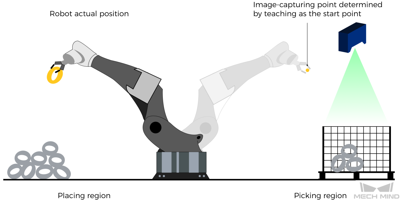
Specific joint positions of the robot |
The robot joint positions of a point determined by teaching must be input to Mech-Viz. The input joint positions are used to trigger Mech-Viz to plan the next path in advance while the robot is not in the camera capture region, as shown below. The simulated robot in Mech-Viz moves from the input joint positions to the first waypoint. |
This setting is recommended for projects in the eye-to-hand mode. |
The reason for setting Robot_Pose_Type to 2 when the project is in the eye-to-hand mode:
In the eye-to-hand mode, the camera can perform image capturing for the next round of path planning before the robot returns to the camera capture region and picking region, shortening the cycle time.
If Robot_Pose_Type is set to 1, the robot’s current pose is sent to Mech-Viz. The simulated robot will move from the input pose to the first waypoint in the planned path, while the real robot might move to another point first, and then move to the first waypoint. Therefore, the path of the real robot may contain unpredicted collisions, leading to safety hazards.
In conclusion, Robot_Pose_Type should be set to 2 for projects in the eye-to-hand mode.
System parameter
Name |
Description |
FromCamera.STATUS_CODE |
If the project is started successfully, the status code 2103 will be returned. Otherwise, the corresponding error code will be returned. |
Example

When there is a rising edge on the parameter Camera_User.Start_Viz, Mech-Viz project will be started, and the current joint positions and flange pose of the robot are sent to Mech-Vision.
Stop Mech-Viz Project
This command is used to stop Mech-Viz project. Please use this command only when there is an infinite loop in the project or the project cannot be stopped properly.

Parameters
Input parameters
Name |
Description |
Stop_Viz |
Stop Mech-Viz project when a rising edge occurs |
System parameter
Name |
Description |
FromCamera.STATUS_CODE |
If the project is stopped successfully, the status code 2104 will be returned. Otherwise, the corresponding error code will be returned. |
Example
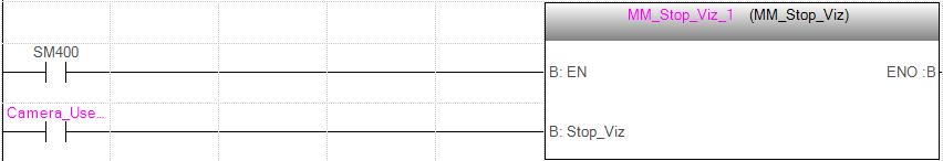
When there is a rising edge on the parameter Camera_User.Stop_Viz, Mech-Viz project will be stopped.
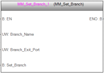
Select Mech-Viz Branch
This command is used to select along which branch the Mech-Viz project should proceed. Such branching is achieved by adding Branch by Msg Step(s) to the project. This command specifies which exit port such Step(s) should take.
Note
MM_Start_Viz must be called BEFORE this command.
When the next Step to be executed in Mech-Viz is a Branch by Msg Step, Mech-Viz will wait for this command to send the exit port number it should take.
Parameters
Input parameters
Name |
Description |
Branch_Name |
Step ID of Step Branch by Msg. The Step ID can be read in the Step’s parameters. |
Branch_Exit_Port |
The selected output port of the Branch by Msg Step |
Please add 1 to the port number displayed in Mech-Viz to get the value here. For example, the port 0 displayed in the interface corresponds to Branch_Exit_Port 1. |
|
Set_Branch |
Specify the port which Branch by Msg Step should take |
System parameter
Name |
Description |
FromCamera.STATUS_CODE |
If the branch is set successfully, the status code 2105 will be returned. Otherwise, the corresponding error code will be returned. |
Example
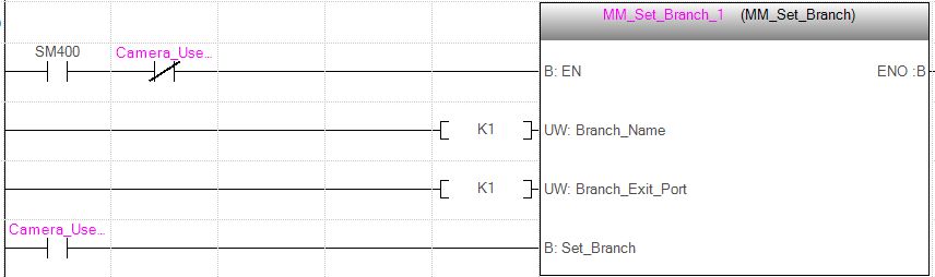
When there is a rising edge on the parameter Camera_User.Set_Branch, Mech-Viz will take exit port 1 for the Branch by Msg Step whose Step ID is 1.
Set Move Index
This command sets the value for the Current Index parameter of Mech-Viz Steps. Steps that have this parameter include Move by List, Move by Grid, Custom Pallet Pattern, and Smart Pallet Pattern.

Parameters
Input parameters
Index_Name
Step ID of the Step with the index parameter. The Step ID can be read in the Step’s parameters.
Index_Counter
The index value that should be set the next time this Step is executed.
When this command is sent, the current index value in Mech-Viz will become the parameter value minus 1.
When the Mech-Viz project runs to the Step specified by this command, the current index value in Mech-Viz will be increased by 1 to become the parameter’s value.
Set_Index
The trigger signal to set the index. The rising edge does the trigger.
Attention
The corresponding relationships of different parameters are as shown in the table below. If the values of the parameters are not the same, they cannot be effective at the same time.
FB/Struct |
Parameter |
|
MM_Set_Branch |
Branch_Name |
Branch_Exit_Port |
MM_Set_Index |
Index_Name |
Index_Counter |
ToCamera |
VIZ_TASK_NAME |
VIZ_TASK_VALUE |
System parameter
Name |
Description |
FromCamera.STATUS_CODE |
If the index is set successfully, the status code 2106 will be returned. Otherwise, the corresponding error code will be returned. |
Example
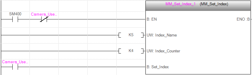
When there is a rising edge on the parameter Camera_User.Set_Index, the Current Index value for the Step whose Step ID is 5 will be set to 4. When the Step is executed, the Current Index value will be added 1 and become 5.
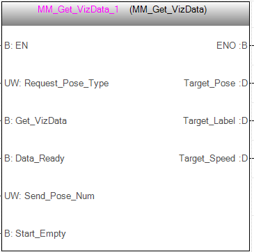
Get Planned Path
This command obtains the planned path from Mech-Viz.
Note
If one of the waypoints in the path is not supposed to be sent to the robot, please clear the parameter “Send Waypoint” checkbox of the corresponding move-type Step.
Parameters
Input parameters
Name |
Description |
Request_Pose_Type |
Whether Mech-Viz should send waypoint poses as joint positions or TCPs, 1 or 2 |
1: Mech-Viz sends joint positions 2: Mech-Viz sends TCPs |
|
Get_VizData |
Obtain planned path from Mech-Viz project when a rising edge occurs |
Data_Ready |
Indicate that all the pose data is available to read when receiving multiple groups of robot poses |
Send_Pose_Num |
The number of waypoints returned by Mech-Viz, from 0 to 20 |
Start_Empty |
Clear the obtained data stored in Target_Pose, Target_Label, and Speed_Percentage. This parameter will take effect when it is set to 1. |
Output parameters
Name |
Description |
Target_Pose |
The waypoint pose in TCP. The data type is array[0..19, 0..5] of DINT. |
The data from this parameter should be divided by 10000 before use. |
|
Target_Label |
The label information of the object recognized by Mech-Vision. The data type is array[0..19] of UDINT. The returned values are integers. |
Target_Speed |
The speed set in the Step related to move, from 1 to 100. |
System parameters
Name |
Description |
FromCamera.STATUS_CODE |
If the planned path is obtained successfully, the status code 2100 will be returned. Otherwise, the corresponding error code will be returned. |
FromCamera.VISUAL_POINT_INDEX |
The position of the vision point, which is generated from the “Vision Move” Step, in the planned path. |
Example
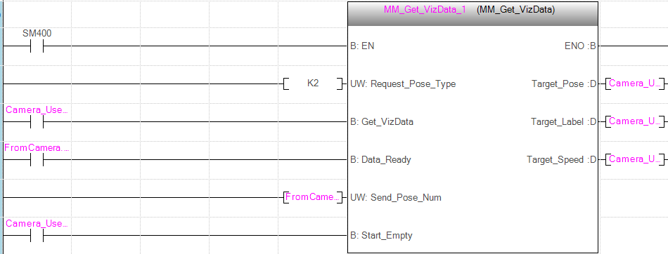
When there is a rising edge on the parameter Camera_User.Get_VizData, waypoints in TCP of Mech-Viz project will be obtained. When Camera_User.Start_Empty is set to 1, data stored in Camera_User.Target_Pose, Camera_User.Target_Label, and Camera_User.Speed_Percentage will be cleared.
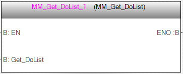
Get DO Signal List
This command obtains the planned DO Signal list for controlling multiple sections of a sectioned vacuum gripper.
Note
MM_Get_VizData must be called BEFORE this command.
Please deploy the Mech-Viz project based on the template project in xxx\Mech-Mind Software Suite-x.x.x\Mech-Center\tool\viz_project\suction_zone, and set the suction cup configuration file in the Mech-Viz project.
Parameters
Input parameters
Name |
Description |
Get_DoList |
Obtain the planned DO Signal list when a rising edge occurs |
System parameters
Name |
Description |
FromCamera.STATUS_CODE |
If the DO Signal list is obtained successfully, the status code 2102 will be returned. Otherwise, the corresponding error code will be returned. |
FromCamera.DO_LIST |
Return 64 DO port values. |
Example

When there is a rising edge on the parameter Camera_User.Get_DoList, the DO signal list planned by Mech-Viz will be stored in DO array.
Input Object Dimensions to Mech-Vision
This command inputs object dimensions to the Mech-Vision project.
Note
This command must be called BEFORE MM_Start_Vis.
The corresponding Mech-Vision project must contain the “Read Object Dimensions” Step, and the Read Sizes from Properties parameter of this step must be checked.
Parameters
Input parameters
Name |
Description |
Vision_Proj_Num |
Mech-Vision Project ID, from 1 to 99 |
External_Input_Box_Dimension |
Dimensions of the object in mm |
Set_Box_Dimension |
Input the object dimensions in the Mech-Vision project dynamically when a rising edge occurs |
Attention
The corresponding relationships of different parameters are as shown in the table below. If the values of the parameters are not the same, they cannot be effective at the same time.
FB/Struct |
Parameter |
MM_Set_Box_Dimension |
External_Input_Box_Dimension |
MM_Set_Pose |
External_Input_Pose |
ToCamera |
EXT_INPUT_DATA |
System parameter
Name |
Description |
FromCamera.STATUS_CODE |
If the object dimensions are set successfully, the status code 1108 will be returned. Otherwise, the corresponding error code will be returned. |
Example

When there is a rising edge on the parameter Camera_User.Set_Box_Dimension, the object dimensions in the Read Object Dimensions Step will be set as the values assigned in External_Input_Box_Dimension[0-2].
Input TCP to Mech-Viz
This command inputs TCP data to the “External Move” Step.
Note
This command must be called BEFORE MM_Start_Viz.
Please deploy the Mech-Viz project based on the template project in xxx\Mech-Mind Software Suite-x.x.x\Mech-Center\tool\viz_project\outer_move, and put the “External Move” Step at a proper position in the workflow.

Parameters
Input parameters
Name |
Description |
External_Input_Pose |
TCP of the robot in mm |
Set_Input_Pose |
Input the poses to Mech-Viz dynamically when a rising edge occurs. |
Attention
The corresponding relationships of different parameters are as shown in the table below. If the values of the parameters are not the same, they cannot be effective at the same time.
FB/Struct |
Parameter |
MM_Set_Box_Dimension |
External_Input_Box_Dimension |
MM_Set_Pose |
External_Input_Pose |
ToCamera |
EXT_INPUT_DATA |
System parameter
Name |
Description |
FromCamera.STATUS_CODE |
If the object pose is input successfully, the status code 2107 will be returned. Otherwise, the corresponding error code will be returned. |
Example

When there is a rising edge on the parameter Camera_User.Set_Input_Pose, the TCP data stored in External_Input_Pose[0-5] will be sent to the External Move Step in the Mech-Viz project.
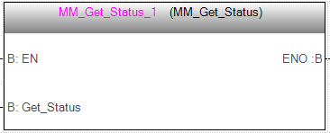
Get Software Status
This command is currently capable of checking whether Mech-Vision is ready to run projects. In the future, this command can be used for obtaining the execution status of Mech-Vision, Mech-Viz, and Mech-Center.
Parameters
Input parameters
Name |
Description |
Get_Status |
Check whether Mech-Vision is ready to run projects when a rising edge occurs. |
System parameter
FromCamera.STATUS_CODE
Software status. 1101 means the Mech-Vision project is ready to run. Other codes mean the project is not ready.
Example
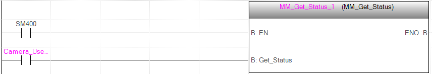
When there is a rising edge on the parameter Camera_User.Get_Status, the system status code will be returned and stored in the parameter FromCamera.STATUS_CODE.