UR CB-Series (Polyscope 3.14 or Above)
This section introduces the process of setting up the Standard Interface communication with a Universal Robots (UR) CB-series robot.
Plugin Installation and Setup
This section introduces the installation and setup of Mech-Mind 3D Vision Interface (URCap plugin) for UR CB-series.
Prerequisites
Verify that you meet the minimum required versions for Mech-Mind vision-series software and Polyscope.
To view the version of Polyscope, press About on the Polyscope home screen of the UR teach pendant.


Install the URCap plugin
To install the URCap plugin, follow these steps:
Find the URCap plugin file with the file extension “1.5.0.urcap” in the
Mech-Center\Robot_Interface\Robot_Plugin\UR_URCAPdirectory of the Mech-Mind Software Suite installation path.Copy the URCap file to a USB drive and insert it into the UR teach pendant.
On the Polyscope home screen, press Setup Robot.
In the Setup Robot window, select URCaps on the left panel.

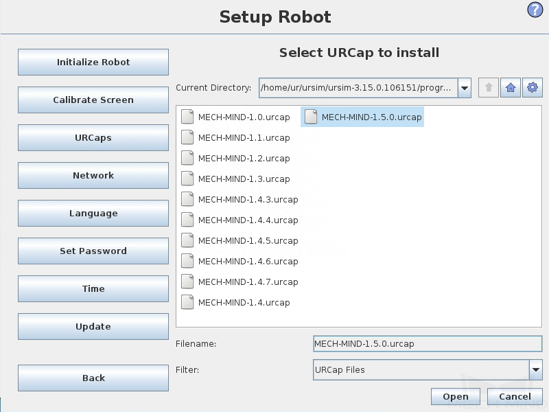
In the URCaps window, press + to navigate to the USB drive to locate the URCap plugin (a .urcap file).
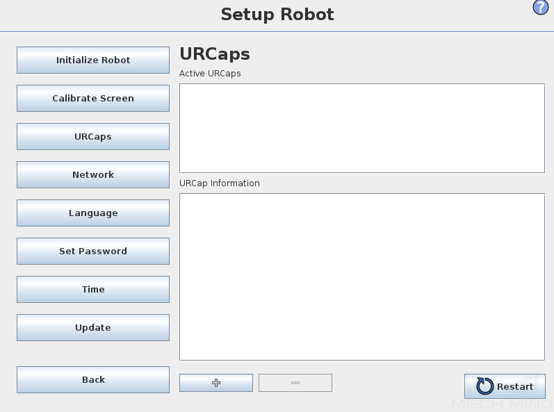
In the Select URCap to install window, select the URCap plugin and press Open. The URCap plugin will be automatically installed.
Press Restart for the change to take effect.

Till now, the URCap plugin is successfully installed on the UR teach pendant.
Attention
After installing the URCap plugin, you also need to set the IP address of the robot (select Set Robot > Network). Note that the robot’s IP address and the IPC’s IP address must be on the same subnet.
Use Mech-Mind 3D Vision Interface
Note
Before use, make sure that your Mech-Vision and Mech-Viz (if used) projects are ready to run, and the Mech-Mind IPC is connected to the robot’s network.
To use Mech-Mind 3D Vision Interface, you need to complete the following setup.
Click Robot and Interface Configuration on the toolbar of Mech-Vision.
Select Listed robot from the Select robot drop-down menu, and then click Select robot model.
Select the robot model that you use, and then click Next.
Select the following options and click Apply.
Interface Type: Standard Interface
Protocol: TCP Server, ASCII
Port Number: 50000 (Cannot be changed)
Make sure the Interface Service is started: on the toolbar of Mech-Vision, the Interface Service switch on the far right is flipped and turned to blue.
After the TCP server interface has been started in Mech-Vision, you can connect to it on the UR teach pendant.
On the Polyscope home screen, press Program Robot.
Select the Installation tab, and press Network Settings on the left panel. The Network Settings window of the URCap plugin is displayed.
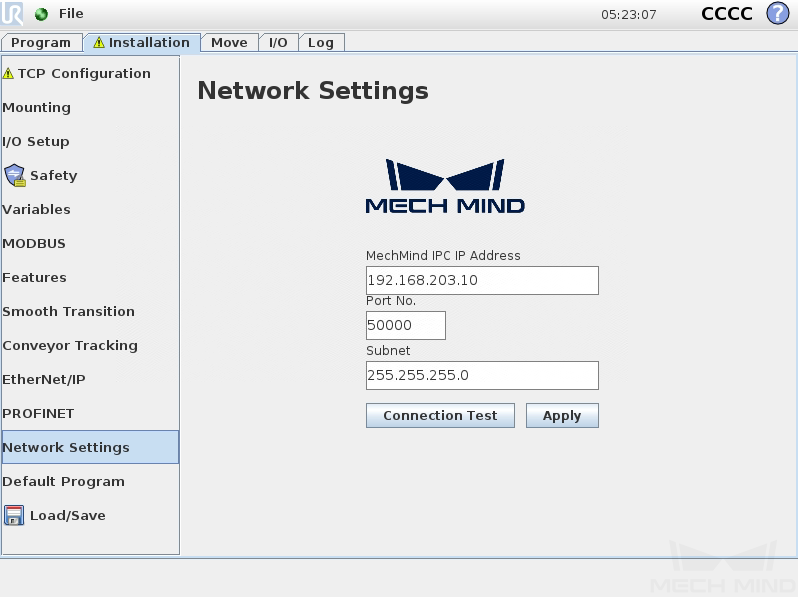
Set MechMind IPC IP Address and Port No. to the IP address and port number of the Mech-Mind IPC respectively, and press Apply.
Press Connection Test.
When the connection to the TCP server interface is established successfully, the return status should look like this:

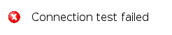
When the connection to the TCP server interface fails to be established, the return status should be like this:
Note
The connection test is just for testing. Once connected, it will disconnect automatically. Therefore, you will see client online and offline logs on the Console tab of Mech-Vision Log panel.
Hand-Eye Calibration Using the Plugin
This section introduces the process of calibrating the camera extrinsic parameters using the URCap plugin.
The calibration process consists of four steps:
Prerequisites
Before proceeding, please make sure that:
You have successfully connected to the TCP server interface with the URCap plugin.
You are familiar with the contents in Hand-Eye Calibration Guide of Mech-Vision.
Create a Calibration Program
On the UR teach pendant, select Program Robot > Program, and press Empty Program.
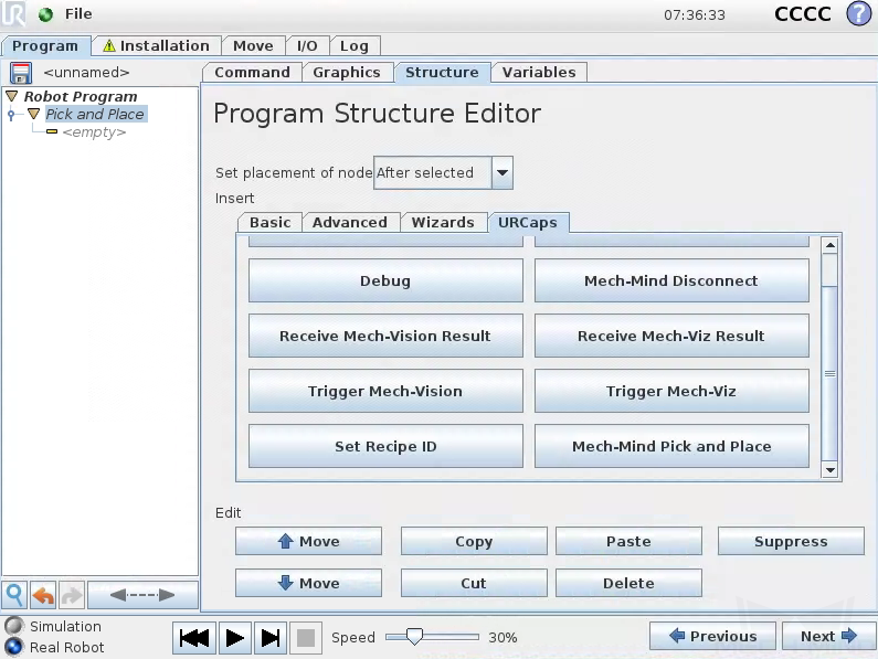
Select Structure > URCaps, and press Mech-Mind Calibrate under the URCaps tab. An example program node Calibrate is automatically created under the Robot Program on the left panel.

The created example program node is just a template. You need to further configure the calibration program and teach the calibration start point.
Teach the Calibration Start Point
Select the Calibrate node in the program tree, press the Command tab on the right panel, and set the Type of point received from Mech-Vision parameter to “Joint Angle” or “Flange Pose” according to the actual needs.

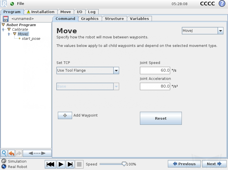
Press Next on the bottom bar to proceed to the MoveJ node, set the motion type to “MoveJ”, “MoveL” or “MoveP”, and Set TCP to Use Tool Flange on the right Move panel to ensure that the waypoint will be recorded as flange pose.
Manually control the robot to move to the start point for the calibration.
On the UR teach pendant, select the start_pose node on the left panel, and press Set Waypoint on the right Waypoint panel. Then you can switch it to the Move tab.
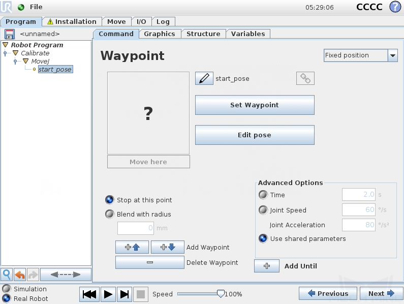
On the Move tab, confirm that the robot’s current flange pose is proper and press OK.

Run a Calibration Program
Select Robot Program on the left panel, and clear the Program Loops Forever checkbox on the right Program panel to ensure that the program is run just once.

On the bottom bar, lower the robot speed to a proper value, such as 10%, for safety concerns.
Press
 on the bottom bar to run the program.
When the calibration program runs successfully, The following message is displayed in the Console tab of Mech-Vision Log panel:
Entering the calibration process, please start the calibration in Mech-Vision.
Complete Calibration in Mech-Vision
In Mech-Vision, click Camera Calibration (Standard) on the toolbar, or select from the menu bar.
Follow the instructions in Mech-Vision to complete the configuration.
If the camera is mounted in the eye-to-hand mode, please refer to Complete Automatic Calibration in the Eye to Hand Scenario.
If the camera is mounted in the eye-in-hand mode, please refer to Complete Automatic Calibration in the Eye in Hand Scenario.
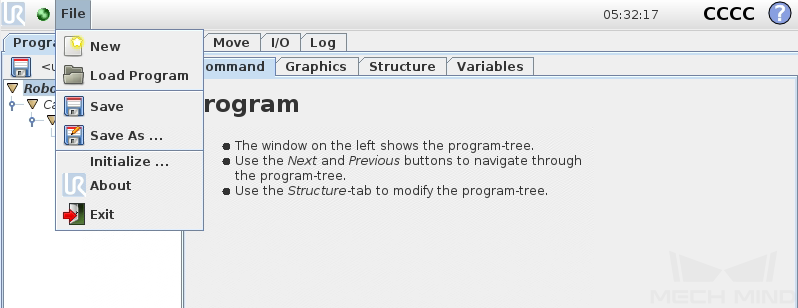
To save the calibration program for future use, select File > Save As to save it.
After you complete the hand-eye calibration, you can create pick-and-place programs to instruct UR robots to execute vision-guided pick-and-place tasks.
Create Pick and Place Programs
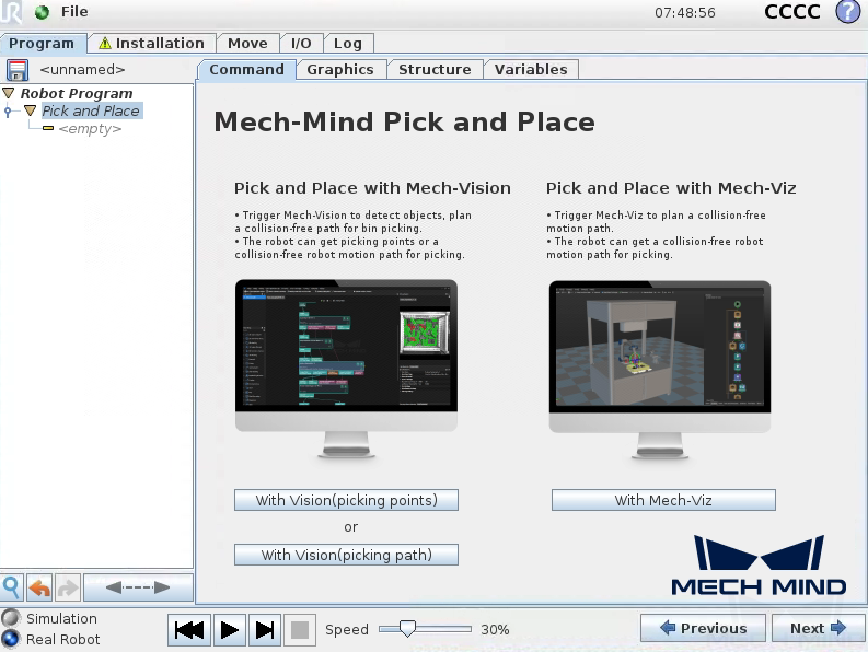
The URCap plugin provides an example Pick and Place program node for you to create pick-and-place programs with minimal programming efforts.
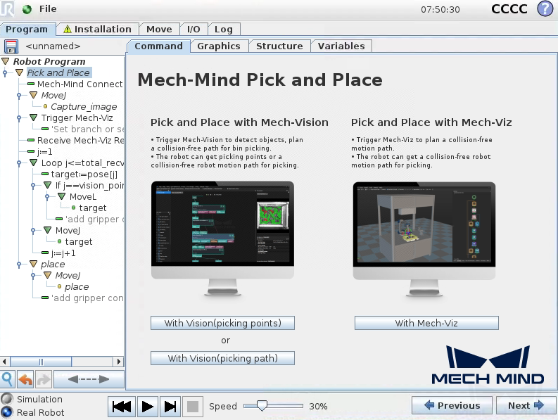
This Pick and Place program node provides three options:
Pick and Place with Mech-Vision (picking points): it suits scenarios where only a Mech-Vision project is used (“Path Planning” Step is not included) and the robot does not need Mech-Viz to plan path.
Pick and Place with Mech-Vision (picking path): it suits scenarios where only a Mech-Vision project is used (“Path Planning” Step is included) and the robot does not need Mech-Viz to plan path.
Pick and Place with Mech-Viz: it suits scenarios where a Mech-Viz project is used together with a Mech-Vision project to provide the collision-free motion path for the robot.
The plugin provides a program template for each option to facilitate the programming.
Note
The following examples assume that the actually used gripper and its TCP have been set for the robot properly.
Create a Pick and Place with Mech-Vision (picking points) Program
To create a Pick and Place with Mech-Vision (picking points) program, follow these steps:
Enable the With Vision (picking points) option.
On the UR teach pendant, select Program Robot > Program > Empty Program.
Select Structure > URCaps, and press Mech-Mind Pick and Place to add a Pick and Place program node to the Robot Program on the left panel.
Select the Command tab, and press the With Vision (picking points) button on the right panel.
When you see that a program template is automatically created under the Pick and Place node in the program tree, press Next on the bottom bar.

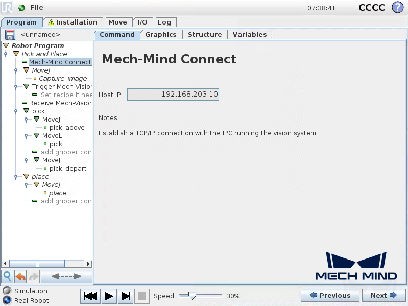
At the Mech-Mind Connect node, verify that the Host IP setting is the IP address of the Mech-Mind IPC on the right Mech-Mind Connect panel.
Set the image-capturing pose.
Manually move the robot to the proper location where Mech-Vision triggers to capture an image.
Note
For Eye-In-Hand scenarios, the robot should be placed above the workpiece.
For Eye-To-Hand scenarios, the robot should not block the camera view.
On the teach pendant, press Next on the bottom bar to proceed to the MoveJ node, set the motion type to “MoveJ”, “MoveL” or “MoveP”, and Set TCP to Use active TCP on the right Move panel, and press Next.

Press Set Waypoint on the right Waypoint panel. Then you can switch it to the Move tab.

On the Move tab, confirm that the robot’s current flange pose is proper and press OK.
Once the image-capturing pose is set, press Next.
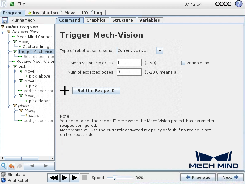
Trigger the Mech-Vision project to run.
Set the parameters Type of robot pose to send, Mech-Vision Project ID, and Num of expected poses on the right Trigger Mech-Vision panel.
Parameter
Description
Type of robot pose to send
Specify the type of robot pose to be sent to Mech-Vision.
Current Position: Send robot poses to Mech-Vision by “Current JPs + Flange”. It is recommended that the project is in Eye-In-Hand mode. In use, the “Path Planning” Step in the Mech-Vision project can send the JPs by the robot. If the flange pose is 0, the flange data will be ignored.
Predefined JPs: Send robot poses to Mech-Vision by predefined JPs (the JPs variable set by the users). It is recommended that the project is in Eye-In-Hand mode. In use, the “Path Planning” Step in the Mech-Vision project can use the JPs sent by the robot as the initial pose.
Mech-Vision Project ID
The index of the Mech-Vision project to trigger. You can find the project ID in the Project List panel of Mech-Vision.
Num of expected poses
The number of vision points that you expect Mech-Vision to output.
If it is set to 0, all detected object poses, but no more than 20, will be output.
If it is set to a number from 1 to 20, Mech-Vision will try to return the fixed number of vision points if the total detected number is greater than the number you expect.
(Optional) Press Set the Recipe ID and a Set Recipe ID node are added under the Trigger Mech-Vision node in the program tree.
Select the Set Recipe ID node in the program tree, set Project parameter recipe ID on the right Set Recipe ID panel, and press Next.

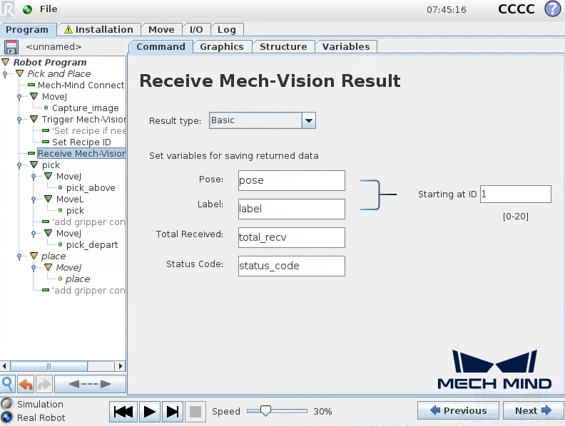
Set how to receive Mech-Vision result.
Select the Receive Mech-Vision Result node under Pick and Place in the program tree, select Result type as Basic, and set variable names for Pose, Label, Total Received, and Status Code, which are used to save the vision result, and then press Next.
Parameter
Description
Result type
Basic: Receive vision point and label. Planned path: Recieve waypoint and label sent from the “Path Planning” Step. Custom: Receive vision point, label, and user-defined port data
Pose
The points of detected parts in XYZ format. The robot can directly move to the point with active TCP. By default, the received points are saved in the array variable “pose[]”, starting with array index 1.
Label
The object labels of detected parts. The label is an Integer. By default, the labels are saved in the array variable “label[]”, starting with array index 1. Labels and Poses are one-to-one paired.
Total Received
The total number of received object poses.
Status Code
The returned status code. See Status Codes and Troubleshooting for reference. 11xx indicates that the status is normal, while 10xx indicates that there is an error. By default, the status code is saved in the variable “status_code”.
Starting at ID
The start index of the array variables for poses and labels. By default, the index starts with 1.
Picking point index
This variable is only displayed in the interface if Result type is Planned path. The index of Vision Move in the received waypoints. For example, the “Path Planning” Step sends 3 points in the order of Relative Move_1, Vision Move_1, Relative Move_2, so the picking point index is 2. By default, the picking point index is saved in the variable “vision_point”.
Custom data
This variable is only displayed in the window if Result type is Custom. It is the user-defined data received from the Steps in Mech-Vision, namely, data of ports other than poses and labels. By default, custom data is stored in the variable “custom_data”.
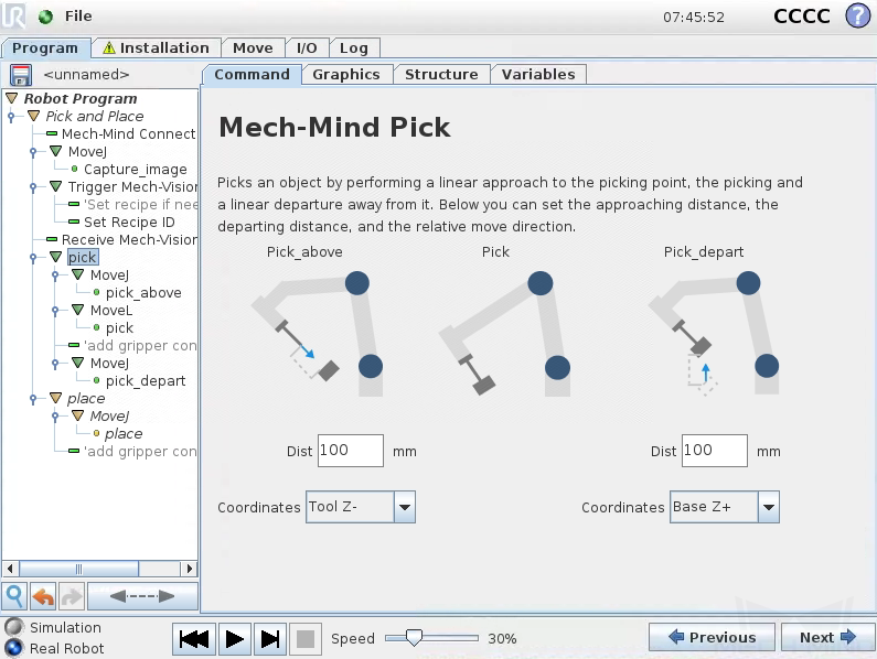
Set the pick task.
Note
A pick task consists of three motions: Pick_above, performs a linear approach to the pick point; Pick, picks the object, and Pick_depart, performs a linear departure away after picking.
Set the parameters Dist and Coordinates for the Pick_above and Pick_depart respectively on the right Mech-Mind Pick panel, and then press Next.
Keep the default settings for the MoveJ node on the right Move panel, and then press Next.
Keep the default settings for the pick_above node on the right Waypoint panel, and then press Next.
Keep the default settings for the MoveL node on the right Move panel, and then press Next.
Keep the default settings for the pick node on the right Waypoint panel, and then press Next.
Add gripper control logic for picking after the pick node according to your actual conditions.
Keep the default settings for the MoveJ node on the right Move panel, and then press Next.
Keep the default settings for the pick_depart node on the right Waypoint panel, and then press Next.
Set the place task.
Press Next to proceed to the next MoveJ node.
Keep the default settings for the MoveJ node on the right Move panel, and then press Next.
Manually move the robot to the proper location to place the picked object.
On the teach pendant, press Set Waypoint on the right Waypoint panel. Then you can switch it to the Move tab.

On the Move tab, confirm that the robot’s current flange pose is proper and press OK.
Once the place pose is set, press Next.
Add gripper control logic for placing after the place node in the program tree according to your actual conditions.
Till now, a simple pick-and-place program with Mech-Vision (picking points) has been completed. You can run it by just pressing on the bottom bar.
Create a Pick and Place with Mech-Vision (picking path) Program
To create a Pick and Place with Mech-Vision (picking path) program, follow these steps:
Enable the With Vision (picking path) option.
On the UR teach pendant, select Program Robot > Program > Empty Program.
Select Structure > URCaps, and press Mech-Mind Pick and Place to add a Pick and Place program node to the Robot Program on the left panel.
Select the Command tab, and press With Vision (picking path).
When you see that a program template is automatically created under the Pick and Place node in the program tree, press Next on the bottom bar.
Set the value of Host IP to the IP address of the Mech-Mind IPC by referring to step 2 in Pick and Place with Mech-Vision (picking points).
Set the image-capturing pose by referring to step 3 in Pick and Place with Mech-Vision (picking points).
See how to trigger the Mech-Vision project to run by referring to step 4 in Pick and Place with Mech-Vision (picking points).
Set how to receive Mech-Vision result by referring to step 5 in Pick and Place with Mech-Vision (picking points).
Attention
Select Receive Mech-Vision Result node in the program tree, and the Result type should be Planned path.
The variable of the Picking point index indicates the index of Vision Move in the received waypoints. For example, the “Path Planning” Step sends 3 points in the order of Relative Move_1, Vision Move_1, Relative Move_2, so the picking point index is 2.
Configure the motion loop, which drives the robot to follow the path planned by the “Path Planning” Step, that is, approach the object, pick the object, and depart from the pick point (not including placing the object). For how to set MoveL and MoveJ nodes, refer to step 6 in Pick and Place with Mech-Vision (picking points).
Note
In actual applications, the motion loop may contain several pick_above MoveJ nodes, a pick MoveL node, and several pick_depart MoveJ nodes.
Set the place task by referring to step 7 in Pick and Place with Mech-Vision (picking points).
Till now, a simple pick-and-place program with Mech-Vision (picking path) has been completed. You can run it by just pressing on the bottom bar.
Create a Pick and Place with Mech-Viz Program
To create a Pick and Place with Mech-Viz program, follow these steps:
Enable the With Mech-Viz option.
On the UR teach pendant, select Program Robot > Program > Empty Program.
Select Structure > URCaps, and press Mech-Mind Pick and Place to add a Pick and Place program node to the Robot Program on the left panel.
Select the Command tab, and press the With Mech-Viz option.
When you see that a program template is automatically created under the Pick and Place node in the program tree, press Next on the bottom bar.

At the Mech-Mind Connect node, verify that the Host IP setting is the IP address of the Mech-Mind IPC on the right Mech-Mind Connect panel.

Set the image-capturing pose in reference to step 3 in Pick and Place with Mech-Vision (picking points).
Note
The point is where to trigger the Mech-Viz project.
Trigger the Mech-Viz project to run.
Set the Type of robot pose to send on the right Trigger Mech-Viz panel.

Note
If the robot pose type is Current Position, the current JPs and flange pose will be sent to Mech-Viz, and the simulated robot of Mech-Viz will move to the first waypoint from the current position of robot JPs. If the robot pose type is Predefined JPs, a predefined JPs will be sent to Mech-Viz, and the simulated robot of Mech-Viz will move to the first waypoint from the current position set by the current robot joint variable.
If you use the branch task in the Mech-Viz project and want the robot to select the branch out port, press Set branch exit port, and proceed to step b to set the branch exit port.
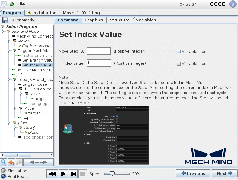
If you use a move-class task that has the index parameter, press Set Index Value, and proceed to step c to set the index value.
(Optional) Select the Set Branch Value node in the program tree, set Branch Step ID and Exit port number on the right Set Branch Value panel, and press Next.

(Optional) Select the Set Index Value node in the program tree, set Move Step ID and Index value on the right Set Index Value panel, and press Next.
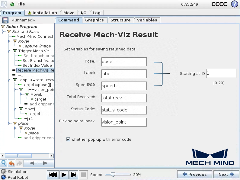
Set how to receive Mech-Viz result.
Select the Receive Mech-Viz Result node in the program tree, and set variable names for Pose, Label, Speed (%), Total Received, Status Code, and Picking point index, which are used to save the planned path, and then press Next.
Parameter
Description
Pose
The planned waypoint pose in XYZ format. The robot can directly move to the point with active TCP. By default, the received points are saved in the array variable “pose[]”, starting with array index 1.
Label
The object labels of detected parts. The label is an integer. For non-vision point, the label should be 0. By default, the labels are saved in the array variable “label[]”, starting with array index 1. Labels and Poses are one-to-one paired.
Speed
The motion speed of the robot moving to the point in percentage.
Total Received
The total received number of waypoint pose.
Status Code
The returned status code. See Status Codes and Troubleshooting for reference. 21xx indicates that the status is normal, while 20xx indicates that there is an error. Default the status code is saved in the variable “status_code”.
Picking point index
The index of Vision Move in the received waypoints. For example, Mech-Viz sends 3 points in the order of Relative Move_1, Vision Move_1, Relative Move_2, so the picking point index is 2. By default, the picking point index is saved in the variable “vision_point”.
Starting at ID
The start index of the array variables for poses and labels. By default, the index starts with 1.
Configure the motion loop, which drives the robot to follow the path planned by Mech-Viz, that is, approach the object, pick the object, and depart from the pick point (not including placing the object). For how to set MoveL and MoveJ nodes, refer to step 6 in Pick and Place with Mech-Vision (picking points).
Note
In actual applications, the motion loop may contain several pick_above MoveJ nodes, a pick MoveL node, and several pick_depart MoveJ nodes.
If you change the default variable names of poses, labels, etc. in the node of Receive Mech-Viz Result, you need to change the variables used in this Step.
Set the place task by referring to step 7 in Pick and Place with Mech-Vision (picking points).
Till now, a simple pick-and-place program collaborating with a Mech-Viz project has been completed. You can run it by just pressing on the bottom bar.