Techman (TM) Standard Interface Commands
The 6 available Standard Interface components are as follows:
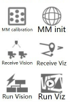
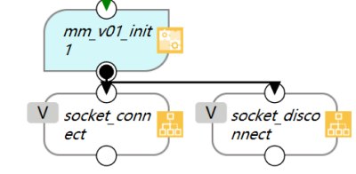
Initialize Communication (MM init)
This component is used to initialize network communication, and it must be added just after the Start Node.
Please refer to Configure the IP Address of the IPC to modify the IP address of the IPC.
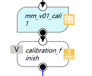
Calibration (MM calibration)
This component is used for camera calibration. It defines the entire process of camera calibration and does not contain adjustable parameters.
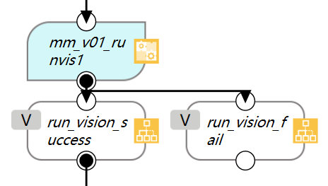
Start Mech-Vision Project (Run Vision)
This component is used to start the Mech-Vision project.
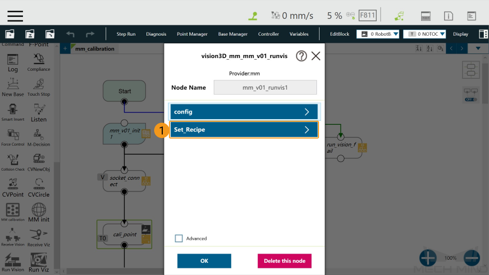
Parameters
config
g_mm_pose_type : Robot pose type
g_mm_point_number : Number of the vision points
g_mm_project_ID : Project ID
Set_Recipe
g_mm_whether_set_recipe : Whether to switch the parameter recipe; true for switching the recipe and false for not switching
g_mm_recipe_ID : The recipe ID
Adjust the Parameters
In the following example, the variables in Set_Recipe are configured.
Click the
 in the upper left corner of the node.
Select the parameter in which you want to configure the parameters.
Select Variables.

Select the variable you want to edit, and click the
 icon.
icon.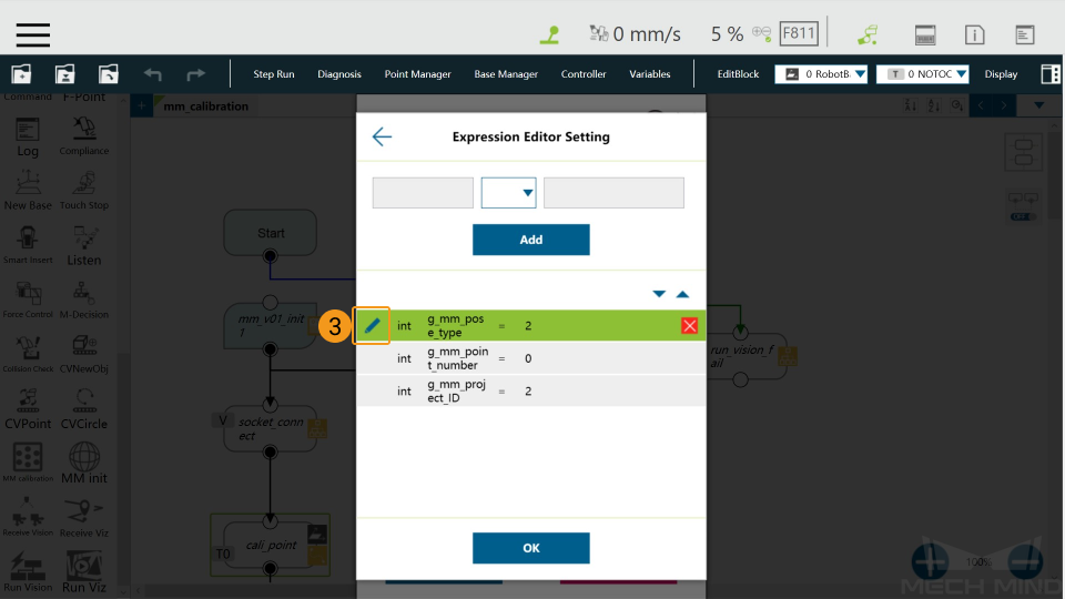
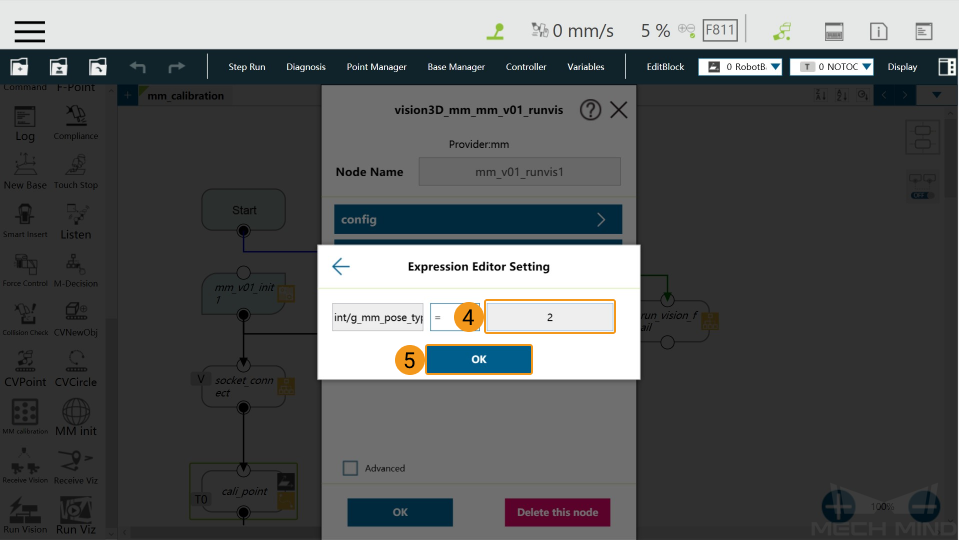
Change the value of the variable in the pop-up window, and click OK when finished.
Start Mech-Viz Project (Run Viz)
This component is used to start the Mech-Viz project.
Parameters
Config
g_mm_runviz_pose_type : Pose type
g_whether_after_161 : Whether the version of Mech-Mind Software Suite is above 1.6.1
Set_Branch
g_mm_whether_set_branch : Whether to set a branch; true for setting the branch and false for not setting the branch
g_mm_branch_task_ID : Step ID the Branch by Msg Step
g_mm_branch_out_port : The number of the exit port to take
Set_Index
g_mm_whether_set_index : Whether to set the Current Index parameter; true for setting the Current Index parameter and false for not setting
g_mm_index_task_ID : Step ID of the Step with the Current Index parameter
g_mm_index_value : Value for the Current Index parameter
Adjust the Parameters
The way to adjust the parameters is the same as described above.
Get Vision Target(s) (Receive Vision)
This component is used to obtain the vision result from the corresponding Mech-Vision project. The sub-node it takes depends on the status code it received.
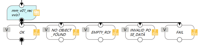
After the execution of this component is complete, the vision result returned from Mech-Vision will be stored in the global variable g_mm_socket_recv_array as strings. You can process the data in the variable according to specific requirements.
Sub-Nodes and the Corresponding Status Codes:
NO_OBJECT_FOUND : 1002
EMPTY_ROI : 1003
INVALID_POSE_DATA : 1006
Get Planned Path (Receive Viz)
This component is used to obtain the planned path from Mech-Viz.
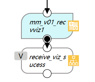
After the execution of this component is complete, the results returned from Mech-Viz will be stored in the global variable g_mm_socket_recv_array as strings. You can process the data in the variable according to specific requirements.
All waypoints are stored in the global variable g_mm_total_point as strings. The first 6 elements in the array represent the first waypoint, and the 7th to 12th elements represent the second waypoint, and so on. The number of waypoints will be added 1 every after 6 elements. You can assign values to the elements in the array to guide the robot to move.
In addition, this component provides a variable g_mm_recv_viz_time that is used to store the number of triggering as integers. The value of the variable starts from 0, indicating that the Get Planned Path component is triggered once. If the component is triggered twice, the variable value will be 1.
Notes
Please follow the steps below to make sure that the network settings of all components are the same.
Drag a component to the Flow Editing Area. Click the
icon in the upper left corner of the node, and select Advanced in the pop-up window.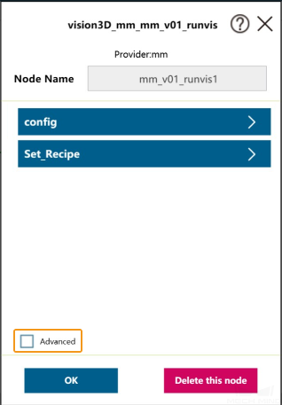
More parameters will be displayed in the window. Click the parameters with send and recv one by one, and select vision3D_mm_mm_v01_init1_ntd_mm in the Network windows.
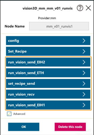

Perform the above operations on all components except MM init to configure the network settings.