3D Simulation Area
The robot, scene objects, tools, workobject models, robot motion path, pick points, and collisions will be displayed in the 3D Simulation Area. Also in this area, you can drag and drop the models of scene objects.
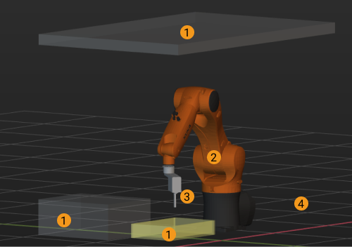
Mouse Actions
You can take the following mouse actions to adjust your view in the 3D simulation area.
Rotate the view |
Hold left button and drag |

|
Display menu for quick view adjustments |
Right-click |

|
Pan the view |
Hold middle button and drag |

|
Zoom in or out |
Scroll |
|
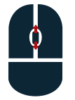
Display Scene Objects
The 3D simulation area displays the following models in a project:
Scene object model
Robot model
Tool model
Ground
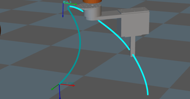
Display Planned Path
Whether for a real scenario or a simulated one, the 3D simulation area can display the planned path of the robot. You can use the displayed path as an aid for adjusting the motion of the robot.
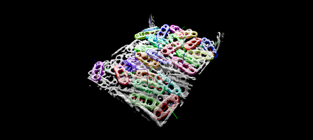
Display Received Vision Result
The vision result received from Mech-Vision is displayed in the 3D simulation area. Generally speaking, a vision result includes: workobject point clouds, scene point clouds, workobject poses, workobject serial number, and customized pose labels that indicate the characteristics of the workpieces.
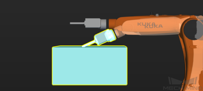
Display Detected Collisions
When planning a path for the robot, Mech-Viz detects whether the robot and/or its tool will collide with scene objects, workpieces, or workobject containers. When a possible collision is detected, the two objects involved in the collision will be displayed with blue highlight and yellow outlines in the 3D simulation area, as shown below.