Calc Parallelism Error
Function
This Step is used to calculate the parallelism error from the target planar point cloud to the reference planar point cloud.
Note
Parallelism is defined as the quality or condition of two planes/edges being parallel. It is measured by the maximum allowable error between one plane/edge and the other.
Parallelism error is the difference between the measured plane/edge and the reference plane/edge.
Hint
Before using this Step, please refer to Getting Started with Measurement Mode to learn about basics of Measurement Mode.
Sample Application

Connect Read Point Cloud V2 with Calc Parallelism Error to calculate the parallelism error from the target planar point cloud to the reference planar point cloud.
Connect Steps
Click on Calc Parallelism Error, go to the Step Input Source Selection panel, and then select Read Point Cloud V2_1_Point Cloud With Normals as Input 1 (Target Planar Point Cloud) and Read Point Cloud V2_2_Point Cloud With Normals as Input 2 (Reference Planar Point Cloud).
Configure parameters
Note
Please prepare the point cloud of the object to be measured and the reference point cloud in advance.
Configure in Read Point Cloud V2 (1)
Click on the Step, and configure the Point Cloud Source (target cloud) and other parameters in the Step Parameters panel.
Configure in Read Point Cloud V2 (2)
Click on the Step, and configure the Point Cloud Source (reference point cloud) and other parameters in the Step Parameters panel.
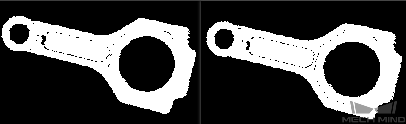
The point clouds used in this sample application are shown below (target cloud on the left and reference point cloud on the right).
Read the result
After running the project, click on Calc Flatness Error and check the parallelism error in the Measurement Output panel.
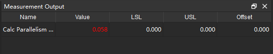
Hint
You can set the LSL (lower specification limit) and USL (upper specification limit) in Measurement Output and Result View panels to check whether the measurement conforms to the specification.