Large Workpiece Measurement Project Creation
This section introduces the project creation framework, processing principles and notes of creating a large workpiece measurement project.
Project Creation Framework
The following Steps and Procedures can be used in sequence to create a large workpiece measurement project.
Obtain the image: Capture Images from Camera
Calc Hole Center Poses and Diameters or Calc Oblong Hole Center Poses and Axis Lengths
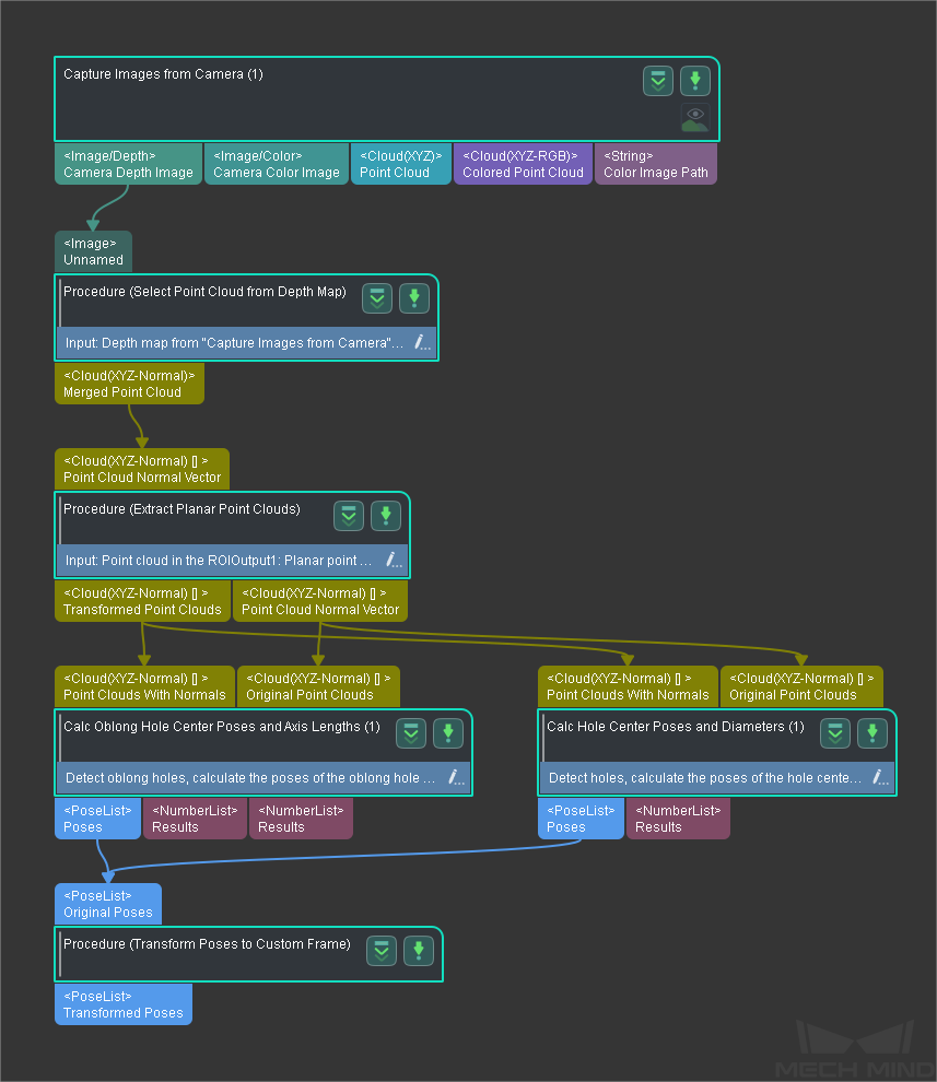
Hint
You should select the Procedure according to the feature of the workpiece. For example, Calc Hole Center Poses and Diameters should be used to measure holes; while Calc Oblong Hole Center Poses and Axis Lengths should be used to measure oblong holes. An incorrectly used Procedure will lead to incorrect measurement results.
Processing Principles
The large workpiece measurement project converts the workpiece poses from the camera reference frame to the base reference frame. The data workflow of the project is as follows:
Capture images with a high-precision camera, and then Mech-Vision will process the images and output the poses of the hole or oblong hole on the workpiece in the camera reference frame.
Create a workpiece reference frame based on the benchmark in the drawing of the workpiece provided by the customer, and then convert the poses from the camera reference frame to the workpiece reference frame.
Convert the poses from the workpiece reference frame to the base reference frame.
Hint
The processing in Mech-Vision is completed after the poses in the base reference frame are output.
Calculate the deviation of the result output by Mech-Vision from the values in the drawings.
Notes
- Large workpiece:
Large workpieces refer to parts that are usually used in automobile, aircraft, ship and other manufacturing industries with lengths longer than 0.5 m.
- Base reference frame:
The reference frame of the object where the workpiece is installed. For example, if the large workpiece is an automobile part, the reference frame of the car body is the base reference frame.
- Hole and oblong hole:
The illustrations are shown as below:
Hole
Oblong Hole


Since each large workpiece may include multiple holes/oblong holes, you can add projects or parameter recipes according to the sequence or feature types of the measurement.