Communication Configuration and Example Program Usage
This topic provides instructions on setting up the Standard Interface communication based on the EtherNet/IP protocol between a Mitsubishi MELSEC iQ-R Series PLC (with the RJ71EIP91 Network Interface Module) and Mech-Mind Software Suite.
Hardware and Software Requirements
Hardware
PLC:
Mitsubishi iQ-R series PLC with the RJ71EIP91 Network Interface Module. An R00CPU module PLC is used as an example in the following instructions.
Power supply: R61P
Base unit: R33B
IPC with HMS IXXAT INpact 40 PCIe interface card installed
USB Type A male to USB Mini-B male cable
Network switch and Ethernet cables
The connection of the hardware system is shown as below.

Software
Software |
Description |
Installed Location |
GX Works3 1.081K |
Mitsubishi PLC sequence programming software |
Computer that is used for PLC sequence programming |
EtherNet/IP configuration software |
Computer that is used for PLC sequence programming |
|
Mech-Mind Software Suite 1.7.0 or above |
Mech-Mind Software Suite |
IPC |
Used for setting up the IP address of the PCIe card |
IPC |
Please copy and paste the following files to a PC with GX Works3 installed.
EDS file: 005A002B003A0100.EDS, which is used to provide the identity information of the IPC in the EtherNet/IP network.
The EDS file is stored in the folder where Mech-Mind Software Suite is installed:
Mech-Center/Robot_Interface/EthernetIP.PLC example program file iQ-R_RJ71EIP91.usl, which contains the following user libraries.
M_RJ71EIP91_Class1SetOutputData_00A: communicates via Class1 to obtain the input data of the specified connection
M_RJ71EIP91_Class1GetInputData_00A: communicates via Class1 to set the output data of the specified connection
CameraSignalsMove: used to transfer the vision system signals
CameraTest: used to test the vision system
MM_XXX_XXX function block: used to implement the functions of various interface commands
The example program files are stored in the folder where Mech-Mind Software Suite is installed:
Mech-Center/Robot_Interface/EthernetIP/Programming Samples/MITSUBISHI iQ-R PLC EthernetIP.
Configure IPC and Initiate Communication
Check PCIe Card and Driver Software
Please make sure that the INpact EIP Slave PCIe interface card has been pressed into the PCIe slot of the IPC.

Start the IPC, go to and check if the driver software VCI4 INpact PCIe has been installed.

Set up “Robot and Interface Configuration” in Mech-Vision
Click Robot and Interface Configuration on the toolbar of Mech-Vision.
Select Listed robot from the Select robot drop-down menu, and then click Select robot model.
Select the robot model that you use, and then click Next.
Select the following options and click Apply.
Interface Type: Standard Interface
Protocol: ETHERNET IP
Make sure the Interface Service is started: on the toolbar of Mech-Vision, the Interface Service switch on the far right is flipped and turned to blue.
Configure IP address of the PCIe Card
Use an Ethernet cable to connect the network ports of the IPC and the INpact EIP Slave PCIe.
Attention
After configuring the IP and initiating communication successfully, the Ethernet cable used here can be removed.
Open HMS IPconfig, click
 and unselect “Retrieve IP settings dynamically from a DHCP server”, and then enter the IP address and subnet mask. After configuration, click Apply and exit the software.
Create and Configure the PLC Project
Create the PLC Project
Open GX Works3, click the New icon on the toolbar. In the New window, set the Series to RCPU, Type to R00, and the Program Language to Ladder, and then click OK.

In the Add a module window, click Setting Change.

In the Options window, select Yes in the drop-down list next to “Use Module Label”, and then click OK. Go back to the Add a module window, and click OK.

In the Current Connection Destination section of the Connection Destination panel on the left, double-click Connection.

A Specify Connection Destination Connection window will pop up.
Select Serial USB on the PC side, and select PLC Module on the PLC side, and RCPU will be automatically filled as the PLC Mode.
Click CPU Module Direct Coupled Setting. Select USB in the pop-up window and click Yes.
Go back to the Specify Connection Destination Connection window, and click Connection Test. If a message Successfully connected with the R00CPU pops up, the GX Works3 software has successfully communicated with the PLC.
Click OK in the Specify Connection Destination Connection window and go back to the main interface of GX Works3.

In the navigation window on the left, expand Parameter and double-click System Parameter, and then a System Parameter window will pop up.
In the I/O Assignment tab of the System Parameter window, select Base/Power/Extension Cable Setting, click the button in the Base column to the right of Main, and a Model Name Selection window will pop up.
In the Model Name Selection window, select the base module and power supply module according to the actual situation, and then click OK.

Click OK in the pop-up window as shown below.

In the I/O Assignment tab of the System Parameter window, select I/O Assignment Setting, click the button in the Module Name column next to 0 (0-0), and an Add New Module window will pop up.
In the Add New Module window, set the Module Type to Network Module and the Module Name to RJ71EIP91, and then click OK in each of the two windows.

Click OK in the pop-up window as shown below.

In the navigation window on the left, expand Parameter and double-click the newly added 0000:RJ71EIP91, and the Module Parameter window will appear.
In the Module Parameter window, select Basic Setting, expand the Own Mode Setting and double-click the blank space next to IP Address.
In the Setting for IP Address window, set the IP address and subnet mask, and click OK.

Download Hardware Configuration to PLC
Select Program in the Navigation panel on the left, and select in the menu bar.

In the Rebuild All window, click Options, and an Options window will pop up.

In the Options window, click Basic Setting on the left, and select Yes for “Reassign Labels in Executing Rebuild All”, and then click OK.
Go back to the Rebuild All window and click OK.

After the program is converted successfully, click in the menu bar.

In the Online Data Operation window, click the Write tab, and click Parameter + Program, and then click Execute.

Click Yes in the pop-up window as shown below.

If the system safety can be ensured, select Yes.

Select Yes to all for “Are you sure you want to overwrite it?”.

After downloading successfully, an alert message as shown below will pop up. If the system safety can be ensured, select Yes.

Click OK in the Completed window. Go back to the Online Data Operation window and click Close.

Reboot the PLC to make the configurations take effect.
Install EDS file and Configure Communication
Go back to the 0000:RJ71EIP91 Module Parameter window, double-click the EtherNet/IP Configuration Tool icon to start the EIP Configuration Tool for RJ71EIP91 configuration software.

An Add New Element window will pop up, enter the IP address of the RJ71EIP91 module, which should be the same as the IP address of the “0000:RJ71EIP91 module parameter” set in GX Works3, and then click OK.

In the EIP Configuration Tool for RJ71EIP91 window, expand the Device Library, and select EtherNet/IP Devices. Click Add and an EDS Management window will pop up.

In the EDS Management window, click Next.

Click Browse, and select the EDS file you need in the pop-up window, and then click Next. Please copy the EDS file from the IPC in advance.

Click Next.

Click OK.

After the EDS file is added successfully, expand EtherNet/IP Device, right-click Ixxat INpact EtherNet/IP(TM), and select Insert in Configuration to connect to the EtherNet/IP network. The Ixxat INpact EtherNet/IP(TM) Revision window will pop up.

Click the General tab and set the IP address of the vision system slave device. The IP address set in this example is 192.168.1.10, which should be the same as the IP address set in HMS IPConfig.

In the Connection tab, click General, and change the value of Input Mode to Point to Point. Then record the value of the Input Size and Output Size, and click OK.

Download PLC EtherNet/IP Network Configuration to PLC
If the “Ixxat INpact EtherNet/IP(TM)” device is added successfully, the device option as shown below will appear in the window. Click the Online command icon on the toolbar.

Select Yes for “Do you want to save the configuration before to go online?” to switch to the online mode.

In the Online communication mode, click the Download the current configuration in the module icon to download the current parameters to the EtherNet/IP communication module RJ71EIP91.

Select configuration.apa in the pop-up window to facilitate the downloading, uploading, and editing of the configuration file with the .apa file extension. Then click Download.

Click OK in the pop-up window as shown below.

Reboot the PLC to make the configurations take effect.
Import Example Program and Download to PLC
Import Mech-Mind Example Programs
Attention
Before you add the example program to a project already in use, it is recommended to import it to a new project and test it first.
Go back to the main interface of GX Works3. Select .

Click OK in the pop-up window as shown below.

In the Register Library to Library List window, select the example program file “iQ-R_RJ71EIP91.usl” and click Open. Please copy the file from the IPC in advance.

Go back to the GX Works3 software window, select two example program files “CameraSignalsMove” and “CameraTest” in the Element Selection panel on the right. Then right-click the example programs and select .

Click Yes in the pop-up window as shown below.

Go back to the GX Works3 software window, check whether the example programs, function block, and labels are imported successfully and appear in the Project panel. Then click in the menu bar.

Click OK in the pop-up window as shown below.

Download PLC Program to PLC
After the programs are converted successfully, click in the menu bar.

In the Online Data Operation window, click the Write tab, and click Parameter + Program, and then click Execute.

Click Yes in the pop-up window as shown below.

If the system safety can be ensured, select Yes in the pop-up window as shown below.

Select Yes to all for “Are you sure you want to overwrite it?”.

After downloading successfully, an alert message as shown below will pop up. If the system safety can be ensured, select Yes.

Click OK in the Completed window. Go back to the Online Data Operation window and click Close.

Check Communication
Go back to the GX Works3 software window, double-click ProgramBody in the Navigation Panel.

Select in the menu bar.

If the connection is established successfully, the monitor value of FromCamera.HEARTBEAT will keep changing.

The PLC is successfully connected if the following message is displayed in the Console tab of Mech-Vision Log panel: Connect to ETHERNET IP controller successfully.
If you don’t see this log message, please check if:
The hardware is properly connected;
If the Interface Service has been started successfully in Mech-Vision;
If the PLC program has been successfully downloaded to the PLC.
Test with Mech-Vision/Mech-Viz Project
This section introduces how to use the example program function block to trigger the Mech-Vision project to obtain vision points and trigger the Mech-Viz project to obtain the planned path.
Prerequisites
Mech-Vision project(s):
Executable
Set to autoload: right-click the solution and select Autoload Solution. Projects in the solution are also autoloaded.
Mech-Viz project:
Executable
Set to autoload: right-click the project name in Resources and select Autoload Project
Contains a “Branch by Msg” Step that has been renamed to 1.
Run Mech-Vision Project and Obtain Vision Points
Configure Programs
Go back to the GX Works3 software window, double-click the program body of CameraTest, and set the status of ToCamera.COMM_ENABLE to be always on.

Click the MM_Start_Vis function block and set the values for the inputs as shown below.
Set the value of Vision_Proj_Num to 1, then project No. 1 in Mech-Vision will be started.
Set the value of Req_Pose_Num to 0, which means the Mech-Vision project will send all the vision points.
Setting the value of Robot_Pose_Type to 0 indicates that the project is in eye-to-hand mode, and the image-capturing pose is not needed.

Trigger Mech-Vision Project to Run
In the window of GX Works3, right-click the Camera_User.Start_Vis label on the input side of MM_Start_Vis, select and modify the value to 1 to trigger the Mech-Vision project to run. Then reset the value to 0.

Check whether the returned value of STATUS_CODE is 1102.
Select in the menu bar.

In the Watch Window 1, find the FromCamera label in the Name column.

Expand the levels and check the returned value of STATUS_CODE.

Attention
If the Mech-Vision project is started successfully, the status code 1102 will be returned. Otherwise, the corresponding error code will be returned. Please refer to Status Codes and Troubleshooting for troubleshooting.
Obtain Vision Points from Mech-Vision
In the window of GX Works3, right-click the Camera_User.Get_VisData label on the input side of MM_Get_VisData, select and modify the value to 1 to get vision points from Mech-Vision. Then reset the value to 0.

Check the returned value of STATUS_CODE in the Watch Window 1.

Attention
If the vision points are obtained successfully, the status code 1100 will be returned. Otherwise, the corresponding error code will be returned. Please refer to Status Codes and Troubleshooting for troubleshooting.
Check the returned value of Target_Pose.
Select in the menu bar.

In the Watch Window 2, find the Camera_User label in the Name column.

Expand the levels and check the returned values of Target_Pose. The example in the figure below received 2 poses. Divide the transferred values by 10000 to obtain the actual pose data.

Run Mech-Viz Project and Obtain Planned Path
Configure Programs
In the window of GX Works3, right-click the Camera_User.Start_Empty label on the input side of MM_Get_VisData, select and modify the value to 1 to clear the previously obtained vision result. Then reset the value to 0.

Check the value of Target_Pose after the vision result is cleared in the Watch Window 2.

Click the MM_Set_Branch function block and set the input values as shown below.
Set the value of Branch_Name to 1, and the Mech-Viz project will execute along the Branch by Msg Step whose Step ID is 1.
Set the value of Branch_Exit_Port to 1, and the Mech-Viz will take exit port 1 for the Branch by Msg Step whose Step ID is 1.

Click MM_Get_VizData, set the value of Request_Pose_Type to 1, and Mech-Viz will send data as joint positions.

Trigger Mech-Viz Project to Run
In the window of GX Works3, right-click the Camera_User.Start_Viz label on the input side of MM_Start_Viz, select and modify the value to 1 to trigger the Mech-Viz project to run. Then reset the value to 0.

Check the returned value of STATUS_CODE in the Watch Window 1.

Attention
If the Mech-Viz project is started successfully, the status code 2103 will be returned. Otherwise, the corresponding error code will be returned. Please refer to Status Codes and Troubleshooting for troubleshooting.
Set Branch Exit Port
In the window of GX Works3, right-click the Camera_User.Set_Branch label on the input side of MM_Set_Branch, select and modify the value to 1 to select the exit port of the branch. Then reset the value to 0.

Check the returned value of STATUS_CODE in the Watch Window 1.

Attention
If the branch is set successfully, the status code 2105 will be returned. Otherwise, the corresponding error code will be returned. Please refer to Status Codes and Troubleshooting for troubleshooting.
Obtain Planned Path
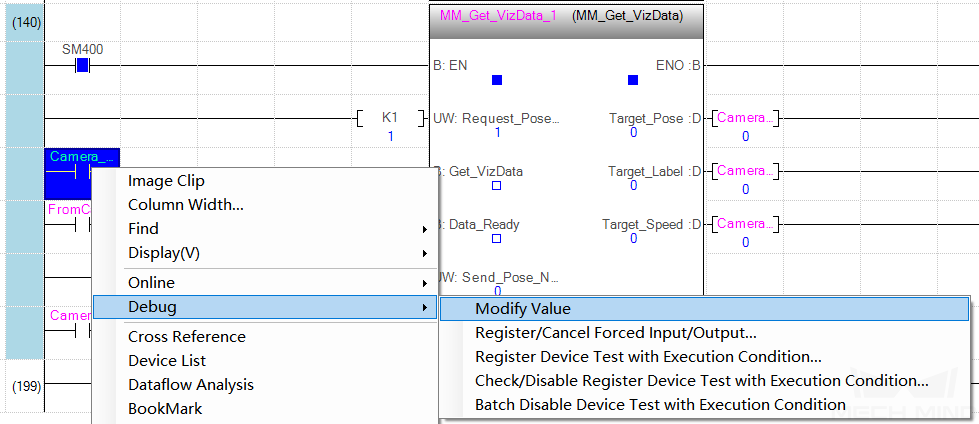
In the window of GX Works3, right-click the Camera_User.Get_VizData label on the input side of MM_Get_VizData, select and modify the value to 1 to get the planned path from Mech-Viz. Then reset the value to 0.
Check the returned value of STATUS_CODE in the Watch Window 1.

Attention
If the planned path is obtained successfully, the status code 2100 will be returned. Otherwise, the corresponding error code will be returned. Please refer to Status Codes and Troubleshooting for troubleshooting.
Click MM_Get_VizData and you can see the value of Send_Pose_Num is 10, which indicates that 10 sets of joint positions are obtained in this example program.

Check the returned values of Target_Pose in the Watch Window 2. Divide the transferred values by 10000 to obtain the actual pose data.
