Adjust Data Display
In the data display area, you can adjust the display of the data through mouse actions, keyboard, and buttons and menus in Mech-Eye Viewer.
Check out the full list of actions you can take for each data type:
Adjust 2D Image Display
Zoom
You can zoom the 2D image in or out by scrolling the mouse wheel while placing the cursor on the 2D image.
To restore the 2D image to the default size: right-click the 2D image and select Reset View.
View Image Information
When you move the cursor on the 2D image, the information of the pixel where the cursor is located is displayed in the lower-right corner.
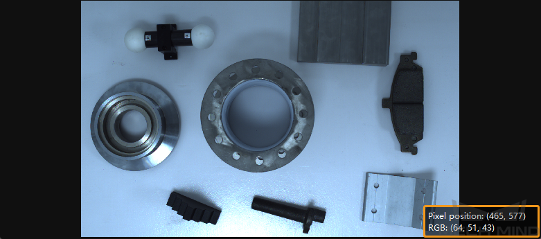
Image information displayed includes:
Pixel position
RGB values (for color 2D image) or grayscale value (for black-and-white 2D image)
You can turn off this display box by unchecking Image Informaiton in the View menu.
Adjust Depth Map Display
Zoom
You can zoom the depth map in or out by scrolling the mouse wheel while placing the cursor on the depth map.
To restore the depth map to the default size: right-click the 2D image and select Reset View.
View Image Information
When you move the cursor on the depth map, the information of the pixel where the cursor is located is displayed in the lower-right corner.
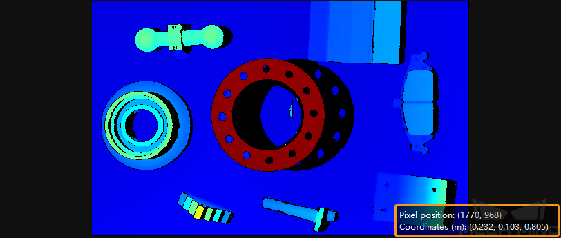
Image information displayed includes:
Pixel position
Coordinates in the camera reference frame (unit: m)
You can turn off this display box by unchecking Image Informaiton in the View menu.
Adjust Depth Data Display
In the left panel of the depth map display, you can change the reference frame, color rendering scheme and range of the depth data.
Change Reference Frame
Select from the drop-down menu of Coordinate System to change the reference frame in which the depth data is displayed.
Camera: Depth data is displayed in the camera reference frame whose origin is located inside the camera.
Customized: Depth data is displayed in the custom reference frame defined with the Custom Coordinate System tool. This tool can be open in the Tool menu.
Change Color Rendering Scheme
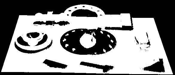
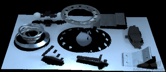
Select from the drop-down menu of Color to change how the depth map is colored. Options include Jet and Gray Scale.
Option |
Description and Example |
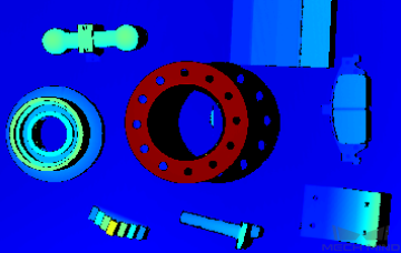
Jet |
Different depth values correspond to different colors in the Jet colormap. |
|
|
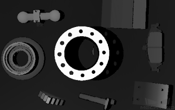
Gray Scale |
Different depth values correspond to different grayscale values. |
|
Adjust Display Depth Range
You can adjust the display depth range in the Range section of the left panel.
Note
The settings here only affect the display. The depth data in the depth map is not trimmed.
Each time that you perform image capturing, the display depth range is automatically adjusted to match the range of the obtained data.
If you want to check the depth fluctuation in a specific interval more closely, you can adjust the display depth range to this interval. The entire color scheme will be re-distributed to this interval, making it easier to check depth fluctuation by color variation.
Click to read an example use case.
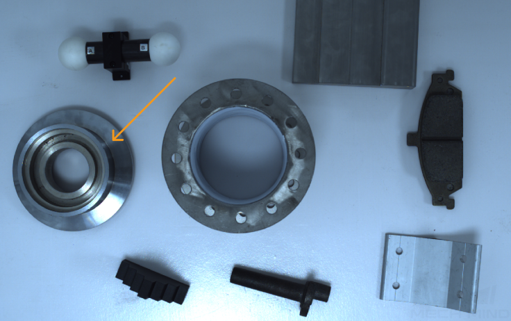
Goal: check if the surface pointed by the orange arrow is flat enough.
Actions:
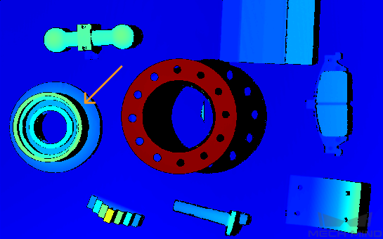
Perform image capturing with
 .
.Switch to depth map display. You can see the surface appears to be roughly the same color. It is hard to tell if the surface is perfectly flat or not.
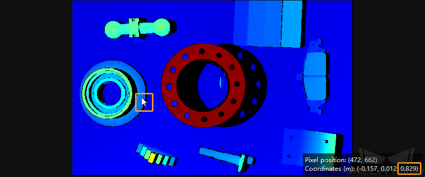
Move the cursor onto the surface to check the z coordinate. Here the z coordinate is 0.829 (unit: m).
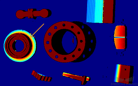
Move the slider handles or change the values in the text boxes to adjust the range to 825–835 mm, a much narrower interval encompassing the above depth value.
Now the depth fluctuation of the surface is easy to see with the color variation.
Depth range: 825–835
Unaltered depth range (725–861)
Note
Depth values outside the set range are displayed as the extreme colors at the two ends.
Adjust the display depth range roughly/quickly: Move the slider handles.
Adjust the display depth range more precisely: Enter the values in the text boxes.
Note
If you are using a UHP series camera, you can change the unit of the depth data to
 from the drop-down menu.
Lock the display depth range: Check the Lock option. When you perform image capturing again, the newly obtained depth map is displayed with the same depth range. This is useful if you want to compare the depth fluctuation in the same interval across different rounds of image capturing.
Note
All functions in the Range section are disabled when Lock is checked.
Reset the display depth range: Click Reset. The range is reset to match the range of the obtained data.
Hint
The Max and Min values at the two ends of the slider correspond to the values set in the Depth Range parameter.
Adjust Point Cloud Display
Zoom and Move
Zoom the point cloud: scroll the mouse wheel while placing the cursor on the point cloud.
Rotate the point cloud: hold the left mouse button and drag the point cloud.
Pan the point cloud: hold the mouse wheel and drag the point cloud.
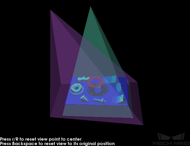
Reset the view to default: press the Backspace key.
Center the view: press the R key. The zoom is reset but rotation is not.
Adjust Depth Data Display
In the left panel of the point cloud display, you can change the reference frame, color rendering scheme and range of the depth data.
Change Reference Frame
Select from the drop-down menu of Coordinate System to change the reference frame in which the depth data is displayed.
Camera: Depth data is displayed in the camera reference frame whose origin is located inside the camera.
Customized: Depth data is displayed in the custom reference frame defined with the Custom Coordinate System tool. This tool can be open in the Tool menu.
Change Color Rendering Scheme
Select from the drop-down menu of Color to change how the point cloud is colored. Options include Jet, Gray Scale, White, and Texture.
Option |
Description and Example |
Jet |
Different depth values correspond to different colors in the Jet colormap. |
|
|
|
Gray Scale |
Different depth values correspond to different grayscale values. |
|
|
|
White |
The point cloud is untextured and displayed as completely white. |
|
|
Texture |
The 2D image is used to texture the point cloud. |
|
Note
When White or Texture is selected, if you switch to the depth map and then back, the Color option is automatically changed to the same one selected for the depth map.
Adjust Display Depth Range
Please refer to Adjust Display Depth Range above for the depth map for detailed information.
Note
When you select White or Texture in Color, adjusting the display depth range will have no effect on the point cloud display. You can see the effect of the adjustment in the depth map display.
Point Cloud Exhibit
This function moves the point cloud along a predetermined trajectory to display it from various angles. It is designed for exhibition and promotion purposes.
To use this function:
Enable the function by checking Point Cloud Exhibit in the View menu.
In the upper-right corner of the point cloud display area, click Play to start the movement.
Note
All other functions are disabled while the point cloud is in motion.
Click the same button (now Stop) to end the movement.
Hint
You can hide the Play button by unchecking Point Cloud Exhibit in the View menu.
Other Actions
Right-click the point cloud for the following options:
Save Point Cloud: save the point cloud in PLY format (unit: m) to a specific path.
Show Frustrum: display the view cones of the projector and 2D camera(s).
Show Axes: display the origin and axes of the selected reference frame.
Continue reading for detailed information on the parameter panel and all the parameters.