3D Workpiece Recognition Visualized Configurator
This section introduces how to use the 3D Workpiece Recognition Visualized Configurator.
Function
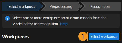
3D Workpiece Recognition Visualized Configurator integrates general vision processing functions. With the following three procedures, you can complete configuring the 3D Workpiece Recognition Step quickly.

Select workpiece: select one or multiple point cloud models from Matching Model and Pick Point Editor as the target workpiece.
Preprocessing: select a region of interest (ROI) for recognition to filter the interference. The algorithm will perform basic processing on the point cloud in the ROI to improve recognition efficiency.
Recognition: adjust the 3D matching parameters in a visual way to make the recognition accuracy and takt meet the requirement. Deep learning can be used to assist the processing if necessary.
Procedure
The procedure for using the configuration tool is as follows.
Select Object
First, click Select workpiece, and the Workpiece Library dialog box will pop up.
Click Model Editor to open the Matching Model and Pick Point Editor.
Create a point cloud model of the workpiece with Matching Model and Pick Point Editor and then exit the tool.
Select one or multiple point cloud models of the workpiece(s) in the dialog box, and then click OK.
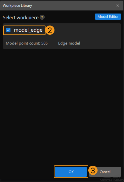
Note
Only the qualified point cloud model of the workpiece will be displayed in the Workpiece Library.
A qualified point cloud model should be added at least one pick point (which can be the geometric center of the workpiece).
After you select the workpiece, click Next to start Preprocessing.
Preprocessing
Click Settings, and set a 3D ROI in the ROI settings window.
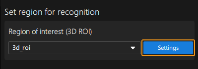
After you finish setting the 3D ROI, click Save and apply.

Then click Run Step, and view the preprocessing result in the visualizing space on the left.
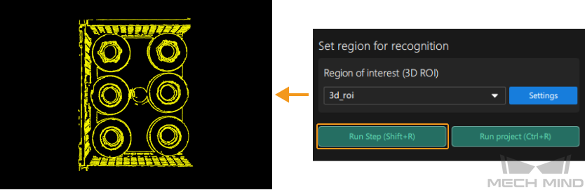
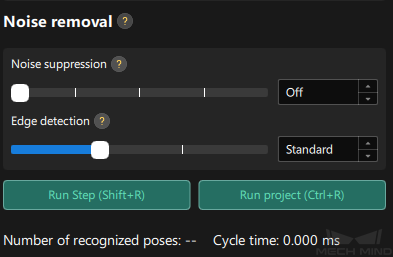
If noises still exist in the recognition area, you can adjust the Noise suppression and Edge detection in Noise Removal. This parameter group is only available for edge matching.
Hint
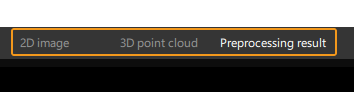
If you want to view the 2D image and point cloud after preprocessing, you can click the tabs of the visualizing space to switch the visualization type.
After the preprocessing, click Next to start the Recognition procedure.
Recognition
In the Recognition procedure, you can adjust the 3D matching parameters in a visual way. The description and tuning recommendation of the parameters are as follows.
Please refer to Parameter Description below for the description and tuning recommendation of the parameters in 3D matching and result judgment.
If deep learning is needed for assistance, select GPU or CPU in the drop-down list next to Assist processing with deep learning, and click Model Package Management Tool.
In the Deep Learning Model Package Management window, import the deep learning model and exit the tool. Then select the deep learning model package in the drop-down list and adjust the Deep learning confidence threshold.
Click Run Step and check the 3D matching result in the visualizing space on the left.
If the recognition accuracy and takt meet the requirement of the project, click Finish, and the 3D Workpiece Recognition Visualized Configurator will be closed.
Note
If you select multiple target workpieces in the Select workpiece procedure, you can click Next workpiece to start configuring the next workpiece.
Parameter Description
3D matching
- Operation approach
- Parameter description: This parameter specifies the operation approach of the matching process. The operation approach determines the relationship between the matching accuracy and matching speed. The higher the matching accuracy, the longer the time required.Value list: High speed, Standard, High accuracy, Extra high accuracy
High speed: applicable to scenarios where workpieces are placed separately or a small number of workpieces are arranged neatly.
Standard: an approach that balances the speed and accuracy, which is applicable to most workpiece loading scenarios.
High accuracy: applicable to scenarios where there is a large number of workpieces or the workpieces are stacked randomly.
Extra high accuracy: applicable to high-precision positioning scenarios.
Default value: StandardTuning recommendation: Please select the operation approach according to the actual requirement for recognition accuracy and speed. - Deviation correction capacity
- Parameter description: This parameter is used to set the intensity of the deviation correction to the matching result. The greater the deviation correction capacity, the more likely the coarsely matched poses can be corrected to the accurately matched poses. Please note that an excessive deviation correction capability may lead to a loss of matching accuracy.Value list: Small, Medium, Large
Small: Applicable to most cases.
Medium: Select according to the actual situation.
Large: Select according to the actual situation.
Default value: SmallTuning recommendation: When there is a relatively large deviation between the matching result and the actual position of the target workpiece, please adjust this parameter. - Symmetry settings
- Description: When a part of the workpiece to be recognized is symmetrical, you will need to adjust the symmetry settings to escape a local optimum of the matching result. An axis of the reference frame with the geometric center as its origin will be specified as the rotation axis, and the point cloud model will rotate around the specified axis according to the symmetry angle step and therefore the optimal matching result can be obtained.Tuning recommendation: The tuning recommendations of parameters are as follows:
Axis of rotation symmetry: This parameter specifies the axis of the reference frame with the geometric center as its origin, and the point cloud model will rotate around the specified axis.
Symmetry angle (0-360): This parameter specifies the angle of rotational symmetry. If an object looks the same before and after rotating 60° around an axis, its angle of rotational symmetry is 60°.
Min rotation angle: This parameter adjusts the minimum rotation angle.
Max rotation angle: This parameter adjusts the maximum rotation angle.
- Pose filtering settings
- Description: When there are abnormal poses in the recognition result, this parameter can be used to filter out the abnormal poses. It is recommended to use this parameter for edge matching.Tuning recommendation: The tuning recommendations of parameters are as follows:
Filter poses by model rotation angle: In the edge matching mode, the point cloud model may need to be rotated by a certain angle to match with the scene point cloud, and the poses will be filtered by the point cloud model’s rotation angle. When the model’s rotation angle exceeds the Angle Difference Upper Threshold, the pose will be filtered out.
Result judgment
- 3D matching confidence threshold
- Parameter description: This parameter is used to determine whether the 3D matching recognition result is valid. If the confidence of the 3D matching recognition result is above the threshold, the result will be considered valid. The higher the confidence value, the more accurate the result is.Default value: 0.300Tuning recommendation: Please adjust the value according to the actual requirement.
- Output count upper limit
- Parameter description: This parameter sets the upper limit of the number of output 3D matching recognition results. If there are multiple 3D matching recognition results, the results will be sorted in descending order according to the 3D matching confidence, and then the results with the highest confidence will be output according to the upper limit specified by this parameter.Default value: 1Tuning recommendation: When there are numerous recognition results, or there is a clear requirement for the upper limit of the output results, please adjust this parameter.
Hint
Only pick point that are also geometric center of the workpiece will be output and visualized.
The actual number of output recognition results is not necessarily equal to the set Output count upper limit. If the Output count upper limit is set to 5, but there are 3 recognition results in total, the final number of output recognition results is 3.