3D Coarse Matching (Multiple Models)
Function
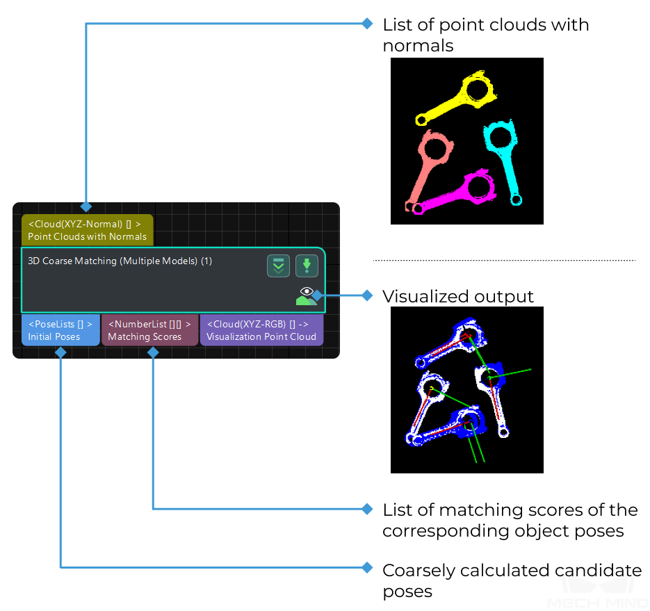
This Step uses multiple models to roughly match objects in the scene, and output the coarsely calculated candidate poses of the target objects.
Usage Scenario
This Step uses multiple models to calculate the original pose of the object, and it can be seen as an extended version of 3D Coarse Matching with a similar method of parameter tuning. This Step can recognize and classify different workpieces.
This Step should be used in multi-model scenarios to distinguish workpieces of different types. This Step is usually followed by 3D Fine Matching (Multiple Models) to obtain accurate poses.
Input and Output
Parameters
Model Settings
The path of model file and pick point file.
- Model File
- Default Value: model.plyInstruction: The path of 3D model file, the construction process can refer to the complete point cloud model stitching document. If the file path or name is changed, the file will be read again when the next time this step is used. The full path or relative path of the model file location can be identified.
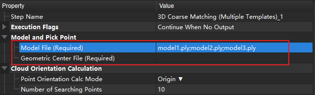
- Geo Center Point File
- Instruction: The pick point file is based on the 3D model file. The pick point file generation method can refer to Add Pick Point by Adding a Pose. If the file path or name is changed, the file will be read again when the next time this step is used. The full path or relative path of the pick point file location can be identified.Example: Ensure that the files entered under each parameter are in the same order, meaning that the Model File has the same path order as the Geometric Center File, as shown in the figure below. Different files are separated by
;.
Cloud Orientation Calculation
- Point Orientation Calc Mode
- Default setting: Origin
List of options |
Instruction |
Origin |
Use the original normal of the input point cloud directly. |
StandardMode |
Use the CPU to recalculate the normal direction of the input point cloud, which is recommended when the model does not have the normal direction. The k points nearest to the target were searched, and PCA (principal component analysis) is used to obtain the minimum feature vector as the normal direction of the point. |
EdgeTangent |
The tangent direction of the input edge point cloud is calculated as the normal direction. Objects whose outer contours are mirror images of each other can be distinguished. It is recommended to match edge point clouds of flat objects. |
EdgeNormal |
Calculate the normal direction of the input edge point cloud, and use the tangential direction of the point as the normal direction, which is recommended for matching the edge point cloud of a flat object. |
Note
When using the EdgeTangent or EdgeNormal methods, ensure that each edge point cloud does not contain multiple objects; in other words, each object point cloud is separated.
- Number of Searching Points
- Default Value: 10Instruction: This parameter is used to adjust the number of adjacent points in the direction of the computed point, which is the value of K in StandardMode mode.
Processor Type
Default Value: SurfaceMatchingEasyModeList of Values: SurfaceMatchingEasyMode, SurfaceMatchingInstruction: There are two types of this algorithm. The algorithm type parameters are adjusted using the figure below as an example, starting with the adjustable parameters in the SurfaceMatchingEasyMode algorithm.SurfaceMatchingEasyMode algorithm: The adjustable parameters module is Speed Controller and Output Settings.SurfaceMatching algorithm: The adjustable parameters module is Sample Settings Voting Sttings and Pose Verification Settings.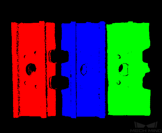
SurfaceMatchingEasyMode
Speed Control
- Main Speed Controller
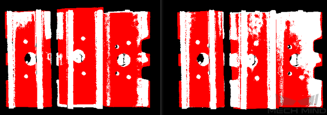
- Default Value: 2Instruction: This parameter is used to adjust the algorithm speed. When the value is increased, the algorithm speed becomes faster, but the matching accuracy decreases. Its effect is more obvious than Secondary Speed Controller .Example of adjustment: As shown in the figure below. The left figure shows the result when this value is
2, and the right figure shows the result when this value is6. It is obvious that the matching accuracy decreases after adjustment.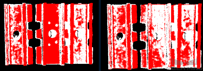
- Secondary Speed Controller
- Default Value: 10Instruction: This parameter is used to adjust the algorithm speed. When the value is increased, the algorithm speed becomes faster, but the matching accuracy decreases. Its effect is weaker than Main Speed Controller.Example of adjustment: As shown in the figure below. The figure on the left shows the result when this value is
10, and the figure on the right shows the result when this Value is15. It can be seen that the matching accuracy decreases after adjustment, but the influence is less than that of the main speed control parameters.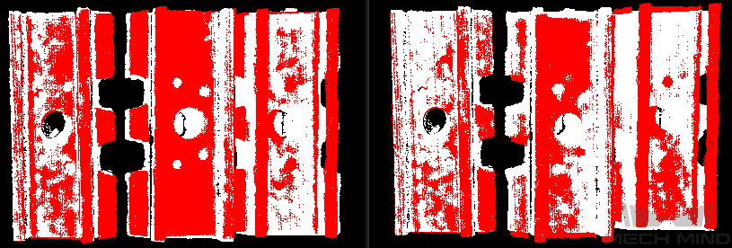
Output Settings
- Maximum Number of Detected Poses in Each Point Cloud
- Default Value: 3Instruction: This parameter is used to estimate the number of matching outputs per point cloud. The larger the value, the more matches are generated.Example of adjustment: As shown in the figure below. The left picture shows the result when the parameter is
1, and the right picture shows the result when the parameter is3.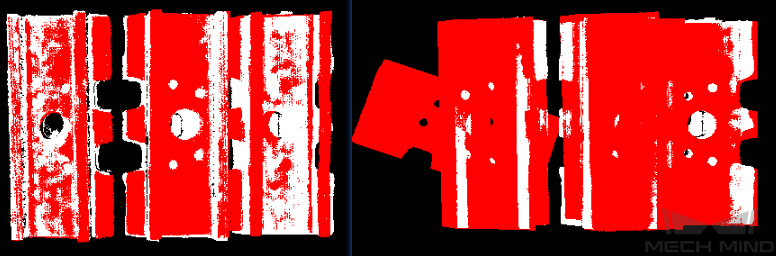
The parameters of SurfaceMatching are described below.
Sample Settings
- Enable Automatic Downsampling
- Default value: SelectedInstruction: This parameter is used to determine whether to use automatic downsampling. If it is selected, the sampling interval parameter of point cloud model will be automatically adjusted according to the expected points of the model after sampling.
- Expected Point Number of Sampled Model
- Default Value: 1000Instruction: This parameter is used to adjust the number of points of the sampling point cloud. It is effective when the value of Enable Automatic Downsamplin is selected, and the number of points of the point cloud is close to this value. The smaller this value is, the fewer points of sampling point cloud are, resulting in the lower accuracy of pose estimation.
- Max Point Number of Sampled Model
- Default Value: 4000Instruction: This parameter is used to set the maximum number of points in the point cloud model after downsampling. It sets an upper limit for the number of points in ourpoint cloud model after downsampling. If the matching effect or matching speed is not ideal, this parameter is recommended to be increased.
- Max Point Number of Sampled Scene
- Default Value: 3000Instruction: This parameter is used to set the maximum number of points in the point cloud after the field point cloud downsampling. It sets an upper limit for the number of points in the field point cloud after the field point cloud downsampling. If the matching effect or matching speed is not ideal, this parameter is recommended to be increased.
- Sampling Interval
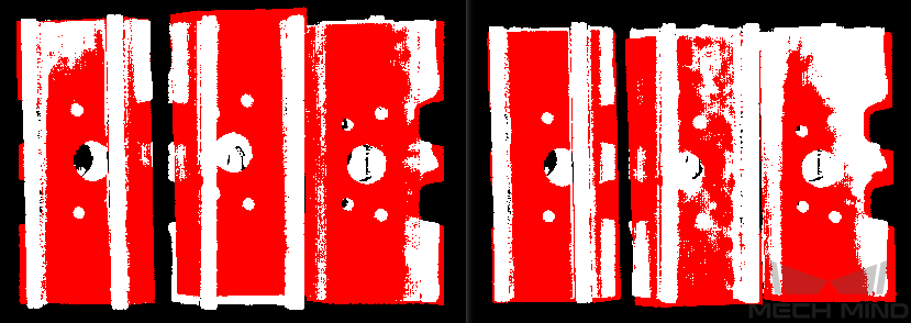
- Default Value: 0.01Instruction: This parameter is used to adjust the maximum distance between points in the sampling point cloud. When the sampling interval of point cloud model is smaller than the minimum sampling interval, the minimum sampling interval is used as the actual sampling interval. The larger the value is, the less point clouds are used for calculation after sampling, the lower the matching accuracy and the lower the algorithm execution time.Example of adjustment: As shown in the figure below. The left picture shows the result when the parameter is
0.01, and the right picture shows the result when the parameter is0.02.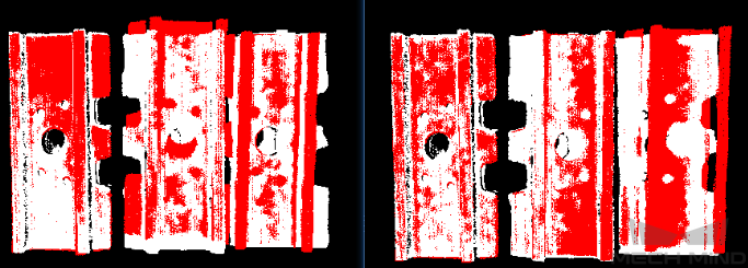
- Min Sampling Interval
- Default Value: 0.003Instruction: This parameter is used to calculate the sampling interval. It is effective when the value of Enable Automatic Downsampling is selected. If the calculated sampling interval is smaller than this value, this value will be used as the actual sampling interval.
Voting Settings
- Distance Quantification
- Default Value: 1Instruction: The value for the quantification of the distance between points (\(Distance Interval = Distance Quantification * Sampling Interval\)). The bigger the value is, the less precise the result tends to be.
- Angle Quantification
- Default Value: 60Instruction: The value for the quantification of the angle between point’s normals (\(Angle Interval = 2 * 3.14 / Angle Quantification\)). The bigger the value is, the less the result tends to do.
- Max Vote Ratio
- Default Value: 0.8Instruction: This parameter sets the threshold for the proportion of the number of votes to the maximum number of votes. The number of votes corresponding to each pose will be obtained in the previous steps, and the maximum number of votes multiplied by this parameter will get a threshold. When the number of votes of a pose is greater than this threshold, the corresponding pose will be retained for clustering operation. The smaller the value, the more likely it is to find an accurate match, but the running time increases.
- Reference Point Step
- Default Value: 5Instruction: This parameter is used to sample points in the point cloud to make a point pairs, from the point cloud with the step size as an interval sampling point. When the value is larger, the interval sampling points are fewer, and the execution speed is faster, but the matching accuracy is reduced.
- Referred Point Step
- Default Value: 1Instruction: This parameter is used to adjust the selection step of the reference point. The step size is taken as an interval sampling point from the point cloud. When the value is larger, the interval sampling points are fewer, and the execution speed is faster, but the matching accuracy is reduced.A referring point and a referred point make up a point pair. The larger the sampling step, the fewer referring points and referred points after downsampling, the fewer the point pairs, and the faster the execution.A reference point is the sampling point on the matching model. A referred point is the sampling point not on the matching model.
Clustering Settings
- Cluster Ratio
- Default Value: 0.1Instruction: This parameter is used to adjust the proportion of the number of poses used for clustering to the total computed poses. Any pose will be given a score during the calculation, and all poses will be sorted according to the score. This parameter determines how much of the pose is used for clustering, A value of 0.1 means that the top 10% pose is taken as the pose for clustering. The larger the value, the more likely it is to find an accurate match, but the running time increases accordingly.
- Threshold of Angle Difference
- Default Value: 15Instruction: This parameter is used to adjust the size of the Angle increment in the clustering process. In the final calculation result, the same object may calculate multiple poses, which determines the increment of the Angle parameter when the poses with very close parameters are fused. The larger the parameter is, the pose with large Angle difference will be fused into the final result, and the matching accuracy will decrease.
- Threshold of Distance Difference
- Default Value: 0.02Instruction: This parameter is used to adjust the size of the Angle increment in the clustering process. In the final calculation result, the same object may calculate multiple poses, which determines the increment of the Angle parameter when the poses with very close parameters are fused. The larger the parameter is, the pose with large Angle difference will be fused into the final result, and the matching accuracy will decrease.
- Output First N Clusters with High Scores
- Default Value: 5Instruction: This parameter is used to take the top N results with the highest score from the multiple matching results obtained after clustering adjustment as the final result.
Pose Verification Settings
- Use Pose Verification
- Default Value: SelectedInstruction: This parameter determines whether pose validation is used. When the parameter is selected, all cluster parameters are invalid. Pose validation and clustering are two different methods for verification and screening of final matching results, which cannot be used simultaneously.
- Marked Margin
- Default Value: 1Instruction: This parameter is used to control the size of the verification area during pose verification. A single voxel is a unit. When the value is increased, the mark area used to verify the pose becomes larger, and more points are included to verify the final result, thus reducing the matching accuracy.
- Voxel Length
- Default Value: 3Instruction: The space where the point cloud is located is divided into a 3D grid, and the parameter is the size of the smallest unit of the 3D grid. When the value is increased, the box selection range becomes larger and there are more selected points for pose verification. In this case, the algorithm speed becomes faster, but the matching accuracy decreases.
- Maximum Number of Detected Poses in Each Point Cloud
- Default Value: 3Instruction: For SurfaceMatching algorithm, this parameter has the same effect as for SurfaceMatchingEasyMode algorithm. Only results are compared here.Example of adjustment: The left side of figure below is the result when the parameter value is
3, and the right side is the result when the parameter value is1.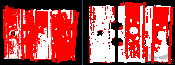
Figure 7 Comparison of Maximum Number Parameter Adjustment Results
Results Visualization
- Show Sampled Model Cloud
- Default value: UnselectedInstruction: This parameter is used to display the downsampled point cloud model.
- Show Sampled Scene Cloud
- Default value: UnselectedInstruction: This parameter is used to display the downsampled field point cloud.
- Show Matching Results
- Default value: SelectedInstruction: This parameter is used to display the matched model and field point cloud.