Caliper Tool
Function
This Step is used to detect edge points or edge point pairs along the vertical direction of an ROI that is usually elongated, and output the pixel-wise coordinates of edge points and distances of edge point pairs (if detecting edge point pairs).
Usage Scenario
This Step is used to measure the widths of specified object parts, or locate edge points along a line over an object. This Step is usually followed by the Convert Lengths Pixel-Wise to Physical Step to get the physical width values.
Input and Output
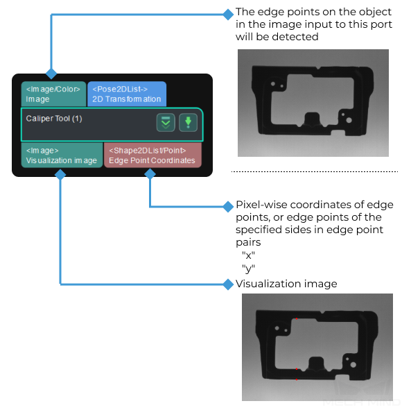
Parameter Description
- ROI
- Description: This parameter specifies an ROI which includes the edge points or edge point pairs, and an elongated frame for edge detection will be generated.Tuning recommendation: You should select an ROI in the measurement mode, please refer to Measure Circles for detailed instructions. When the image quality is good, you can set the Width of the ROI to 1, and adjust the Height to cover the area to be detected.
- Position and Orientation Correction
- Description: This parameter is used to adjust the ROI to a proper position.Notes: Once this parameter is selected, the Step will adjust the ROI set before to a proper position according to the input “2D poses”.
- Grayscale Change Lower Threshold
- Description: This Step is used to specify the lower threshold of the grayscale change of the point in the detection area. If the point’s grayscale change is above this threshold, the point will be considered as an edge point.Default value: 20
- Sigma of Gaussian Filter
- Description: Gaussian filter is used to remove noise from the image. This parameter is used to set the coefficient of the filter along the vertical direction in the edge detection area.Default value: 1.0Recommended value: 1.0Tuning recommendation: If the image quality is good, you can keep the default value 1. If the image quality is poor, you can use a larger value.
- Max Number of Results
- Description: This parameter specifies the maximum number of edge points or edge point pairs output by this Step.
As for edge points, the edge point with greater grayscale change will be output with priority.
As for edge point pairs, the edge pair in which the distance between two edge points that is closer to the Edge Pair Expected Distance will be output with priority.
Default value: 1Tuning recommendation: Please adjust the value according to the actual requirement. - Output Order
- Description: This parameter specifies in which way the detection results will be sorted and output.Value list: Top to Bottom, Bottom to Top, Center to Ends
Top to Bottom: Edge points that are closer to the top of the ROI will be ranked high on the output list.
Bottom to Top: Edge points that are closer to the bottom of the ROI will be ranked high on the output list.
Center to Ends: Edge points that are closer to the center of the ROI will be ranked high on the output list.
Default value: Top to Bottom - Edge Mode
- Description: This parameter specifies the mode of the edge to be detected.Value list: Single Edge, Edge Pair
Single Edge: Detect a single edge only, and output a list of individual edge points.
Edge Pair: Detect edges on both sides, and output two lists of edge points respectively, which represent edge point pairs.
Default value: Single EdgeNotes: Please refer to tuning examples for the visualized output.Hint
When the edge mode is Edge Pair, you will need to set all the Edge Transition Type 0, Edge Transition Type 1 and Edge Pair Expected Distance parameters.
- Edge Transition Type 0
- Description: Edge transition type is used to specify which kind of edge with the grayscale change will be considered as the object edge. This parameter is used to detect single edge points or edge points on one side in the edge point pairs.Value list: White To Black, Black To White, Both
White To Black: The position in the ROI where the grayscale changes from white to black will be considered as the edge point of the object.
Black To White: The position in the ROI where the grayscale changes from black to white will be considered as the edge point of the object.
Both: The position in the ROI where the grayscale changes from black to white or from white to black will be considered as the edge point of the object.
Note
The grayscale change refers to the change in grayscale from top to bottom in the ROI.
Default value: White To BlackNotes: Please refer to tuning examples for the visualized output. - Edge Transition Type 1
- Description: Edge transition type is used to specify which kind of edge with the grayscale change will be considered as the object edge. This parameter is used to detect the edge points on the other side in the edge point pairs. You need to set this parameter when the edge mode is Edge Pair.Value list: This parameter is the same as that of Edge Transition Type 0.
- Edge Pair Expected Distance
- Description: This parameter is used to specify the expected distance in pixels between two edge points of an edge pair.Default value: 10Notes: The edge pair in which the distance between two edge points that is closer to this value will be output with priority.
Hint
Once a Max Number of Results is set, the edge point pairs with lower priority may be ignored.
Tuning Examples
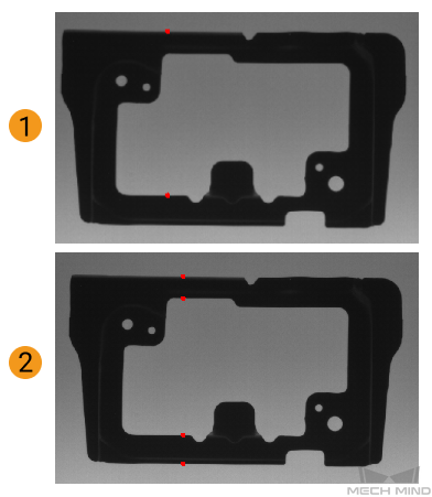
Edge Mode
When the Edge Mode is set to Single Edge and Edge Pair respectively, the output results are shown in the figure 1 and 2 below.
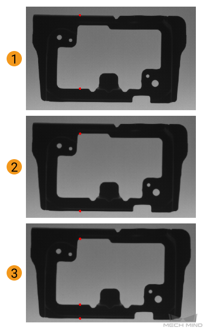
Edge Transition Type
When the Edge Transition Type is set to White To Black , Black To White , and Both respectively, the output results are shown in the figure 1, 2 and 3 below.