Custom Coordinate System
You can define a custom reference frame in Custom Coordinate System for displaying the depth information of depth maps and point clouds.
Click in the menu bar to access this tool.
Note
The custom reference frame is for display in Mech-Eye Viewer only. The depth values stored in the saved depth map and point cloud are unchanged.
Suitable Scenarios
Under certain circumstances, the camera cannot be mounted directly above the target objects, but has to capture images at an angle, as shown below.
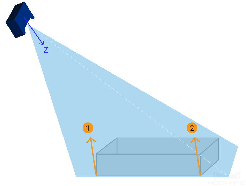
In such cases, the Z-axis of the camera reference frame isn’t perpendicular to the object plane. Therefore, two points that appear to be at the same height in the eyes of an observer, such as points 1 and 2 in the figure above, will have different depth values in the obtained depth maps and point clouds.
When you perform image capturing with a camera mounted at an angle, the obtained 2D image and depth map will look like the following:
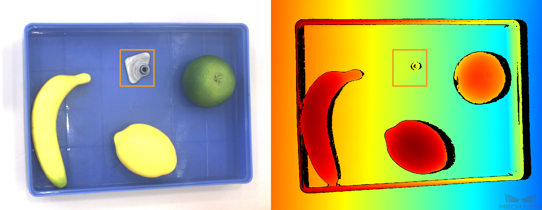
A surface horizontal to the observer’s eyes, such as the bottom of the bin, will have varying depth from left to right. A flat, thin object, such as the one in the orange box, seemingly disappears in the depth map, because its own thickness is too small compared to the background depth variation.
To resolve this discrepency between observed height and obtained depth data, you can define a custom reference frame in Custom Coordinate System. Once an appropriate custom reference frame is defined, the depth data will appear to be consistent to object heights that you see.
Define a Custom Reference Frame
Basic Principle
In Custom Coordinate System, you can define a reference frame by selecting three points:
The first selected point is the origin of your custom reference frame.
The second and first points together define the X-axis.
All three points together define the XoY plane.
The third point’s relative position to the X-axis determines the positive direction of the Y-axis.
The Z-axis is then determined through the right-hand rule.
Hint
To ensure that the displayed depth information is consistent with what you actually see, select the three points on a plane that appears to be horizontal to you.
Instructions
Open Custom Coordinate System, press down the Shift key while clicking three points on the displayed point cloud.
Hint
Scroll to zoom in/out, drag to rotate the point cloud, and drag with the scrolling wheel to move your point of view.
After selecting the three points, the axes of the custom reference frame will appear on the point cloud. Rotate the point cloud to check:
If the Z-axis is perpendicular to the plane that appears horizontal to you.
If the Z-axis is pointing in the direction you want. If not, choose the third point on the other side of the X-axis defined by the first two points.
If the custom reference frame doesn’t meet your needs, click Reset to clear the reference frame and re-select the points.
Click OK to save the custom reference frame.
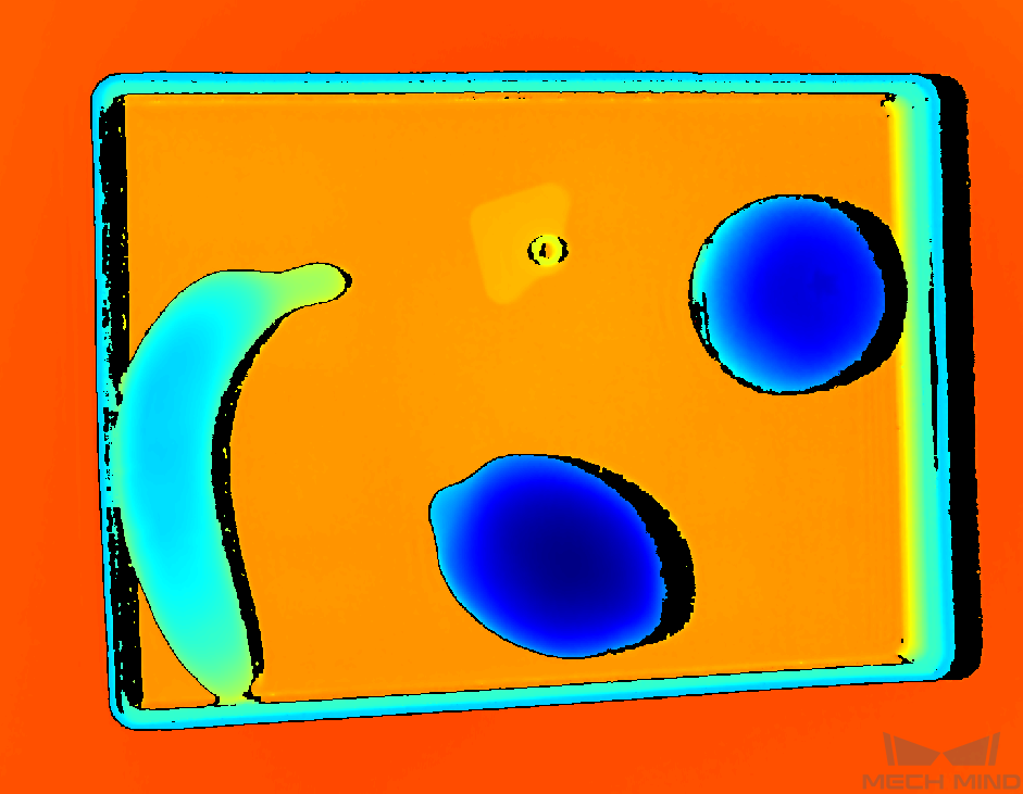
For the following section, a custom reference frame is defined to have the XoY plane on the surface where the bin is placed:
Use the Custom Reference Frame
Once you have a custom reference frame defined, perform image capturing again with
 or
or  .
.In the Image Display area, select Depth Map or Point Cloud. In the left panel, select Customized from the drop-down menu of Coordinate System.
Now the depth information is displayed in the custom reference frame: the bin bottom has the same color that represents the same depth.