Fundamentals
Project
Projects refer to the robot path planning projects created in Mech-Viz. Once you have completed the necessary setup of the project, you can use the project to plan a path and guide the robot to move. All the configurations of the project are stored in the folder with the same name as the project.
Project Resources
Project resources refer to various fundamental resources used in the project, including the robot, tools, workobjects, and scene objects.
- Robot
In Mech-Viz, robots refer to multi-joint robotic arms or the automated truss system for industrial use.
- Tools
Tools, such as grippers and suction cups, are specially designed mechanical devices attached to the flange of the robot to perform various tasks.
- Workobjects
Workobjects refer to the objects on which the tool performs tasks, such as cartons, metal parts, parts to be glued or welded, etc.
- Scene Objects
Scene objects, usually including the safety fence, picking bin, tray, camera, camera stand and so on, refer to objects in the real scenarios where the robot performs various tasks.
Workflow
Workflow refers to the robot motion control program created using visual programming in Mech-Viz.
Reference Frame
The following reference frames are involved in a Mech-Viz project.
- World Frame
A reference frame whose origin is the center of the 3D simulation area. The position of this reference frame will not change.
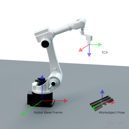
- Robot Base Frame
A reference frame whose origin is on the bottom side of the robot base. The position of this reference frame will move with the robot. The vision results will be converted to the robot base frame using extrinsic parameters of the camera. By default, the robot base frame coincides with the world frame.
- Robot TCP Frame
A reference frame whose origin is at the tool center point.
- Scene Object Frame
A reference frame whose origin is at the center of the scene object model. Every scene object has an individual scene object frame.
TCP (Tool Center Point)
The tool center point (TCP) is on the tip of the tool.
In order to complete tasks such as picking, we usually say that the robot should move to a specific point in space, which actually means its TCP should move to that point.
Workobject Pose
The workobject pose is the pose of a certain point on the workobject, which is the working point of the tool, relative to the base of the robot.
Attention
The direction of the Z-axis of the workobject pose must be the opposite of the direction of the Z-axis of the TCP during the grasping process.
Rotational Symmetry of the Tool
A rotational symmetric tool will coincide with itself after rotating around its axis of symmetry.
Rotational Symmetry of the Workobject
A rotational symmetric workobject will coincide with itself after rotating around its axis of symmetry.
Please refer to Rotational Symmetry of the Workobject for detailed information.
Workobject Picking Relaxation
When the robot picks certain workobjects, the picking pose of the robot is allowed to be changed flexibly within a specific angle range, which is the picking relaxation.
Please refer to Picking Relaxation for detailed information.
Joint Positions (JPs)
A joint position, commonly known as joint angle, is the position of one joint of the robot. Joint positions are a set of parameters, and the number of sets of parameters equals the number of joint axes. For example, the set of joint positions of a six-axis robot is 6.
Pose
The position and orientation of objects in space are collectively called poses. The pose is expressed in translation and rotation (quaternions or Euler angle).
Pick Point
Pick point is the position on the object that can be grasped by the robot.
Picking Pose
Picking pose is the pose of the robot (in the form of JPs or TCP) when it picks the workobject.