Rotational Symmetry of the Workobject
This section introduces the rotational symmetry of the workobject.
Introduction
Note
The “symmetry” in this section refers to “rotational symmetry”.
A rotational symmetric workobject will coincide with itself after rotating around its axis of symmetry. If a workobject has rotational symmetry, you can configure the rotational symmetry parameters according to the specific requirement in the Workobject Configuration window. Configuring the rotational symmetry of the workobject can prevent the end of the robot from rotating meaninglessly when picking and placing, and therefore the picking success rate can be increased and the planning time can be reduced. Therefore, the robot can move more smoothly and swiftly.
Rotational Symmetry
Determine the Axis of Symmetry
The axis of symmetry is one of the axes of the workobject’s geometric center set in Matching Model and Pick Point Editor. The axis of symmetry is not unique. For the same workobject, there can be multiple geometric centers due to different workobject positions and tool types, and therefore the determination of the axis of symmetry will be affected as well.
The table below shows the symmetry types of some workobjects that are placed in a common way. If you are not sure about the axis of symmetry of the workobject you use, please refer to Geometric Center Settings for more information.
Non-Symmetrical
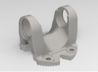
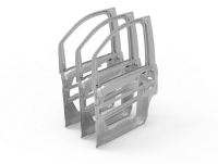
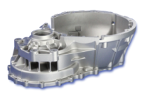
The workobjects in the table below are non-symmetrical workobjects.
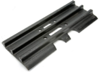
Track pad of the bulldozer
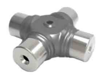
Drive shaft flange yoke
Sheet metal of the car door
Transmission bell housing
Symmetrical about the Z-Axis
When the workobjects are placed in a normal way, workobjects as shown in the table below are symmetrical about the Z-axis.
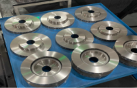
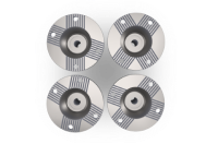
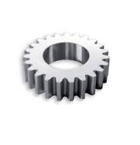
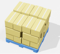
Disc brake
Flange
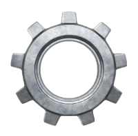
Gear
Carton
Symmetrical about the X/Y-Axis
When the workobjects are placed in a normal way, workobjects as shown in the table below are symmetrical about the X/Y-axis.
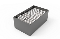
Highly reflective steel rods that are arranged neatly
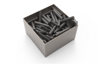
Steel rods that are stacked randomly
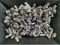
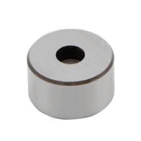
Oil pipe inserts
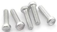
Bolts
Number of Folds
A rotational symmetric workobject will coincide with itself after rotating around its axis of symmetry by a certain degree (i.e., angle of rotation a°), and the number of folds N = 360°/a°.
For a common carton, N = 2; for a triangular prism, N = 3; for a cylinder, N = Infinity (i.e., circular symmetry in the software).

|
|
|
|
N = 2 |
N = 4 |
N = 9 |
Circular symmetry |
Attempt Range
As shown in the figure below, the angle between B and C represents the attempt range.

“A” represents the picking pose when the tool is at the pick point, “B” and “C” represent the pose when the tool picks at the margin of the picking relaxation.
Please set the attempt range according to the workobject position, shape of the bin, tool type, takt time and other factors. An overly large attempt range may increase the planning time; while an overly small attempt range may result in missing the feasible pick point.
Number of Attempts
The number of attempts is calculated automatically from the number of folds and attempt range.
Assuming that the number of folds N = 10, and the attempt range is ±80°, then the angle of rotation can be calculated by 360°/10 = 36°. The number of attempts in one direction can be calculated by 80/36 = 2 and the remainder is 8, which is 2 attempts by the degree of 36° and 72°. The total number of attempts equals 1+2*2 = 5, which are by the degrees -72°, -36°, 0°, 36°, and 72°.