Calibration Principles
This topic describes the working principles of calibrations in different scenarios.
Calibration in the ETH Scenario (Multiple Random Calibration Board Poses)
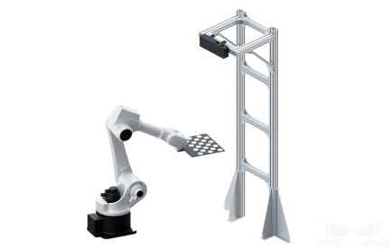
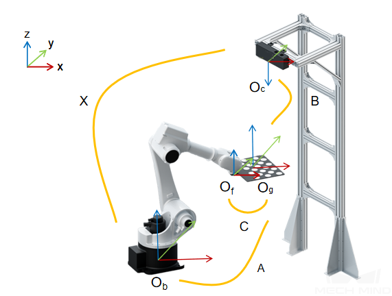
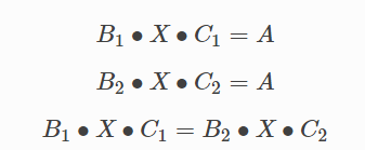
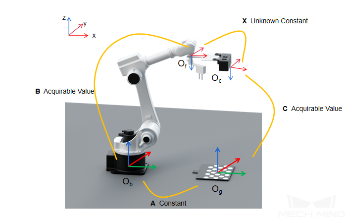
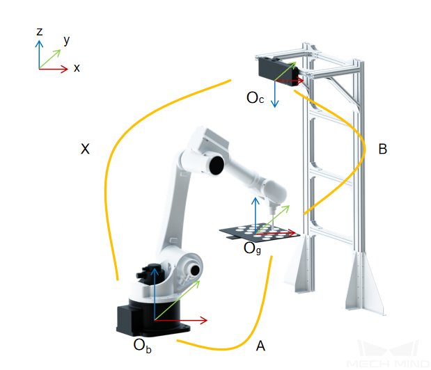
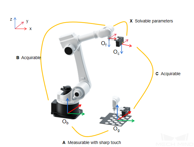
A calibration board of known dimensions is installed on the robot flange, and the coordinates of each circle on the calibration board, denoted by A, in the robot base reference frame, can be obtained. By capturing images of the calibration board, the coordinates of the camera’s optical center relative to each calibration circle, denoted by B, can be obtained. The transformation relationship between the reference frames of the camera’s optical center and the robot base, denoted by X, is the unknown variable. Thus, A, B and X form a closed loop, and the value of X can be calculated through the equations generated from the loop. The spatial relationship between the calibration board and the robot flange, denoted by C, is unknown. Through movements of the calibration board during the calibration process, C can be obtained, which can be used to calculate A. By moving the robot, multiple poses of the calibration board can form a set of equations, which give an optimal value of X by numerical fitting and optimization algorithm. This is shown in the following figure.
Equations for calculating the transformation relationship between the camera and robot reference frames are shown in the following figure.
Calibration in the EIH Scenario (Multiple Random Calibration Board Poses)
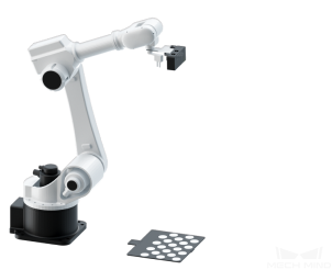
In this scenario, the camera is mounted on a flange that is fixed at the end of the robot. The spatial relationship between the center of the flange and the camera’s optical center, denoted by X, is an unknown constant. The pose of the flange in the robot base reference frame denoted by B, is a known variable. The spatial relationship between the camera’s optical center and each circle on the calibration board, denoted by C, can be calculated by capturing images of the calibration board with the camera. The calibration board is placed within the camera’s field of view. The pose of the calibration board in the robot base reference frame, denoted by A, is a measurable constant. Thus, A, B, C, and X form a closed loop. In the equations, since A is a constant, when the first two equations are combined, X will be the only unknown variable. As the robot moves to different poses, the camera will capture images from different angles and produce multiple sets of A, B, and C. Then, these values can be used to perform numerical fitting and obtain an optimal solution of X.
Equations for calculating the transformation relationship between the camera and robot flange reference frames are shown in the following figure.
Calibration in the ETH Scenario (TCP Touch)
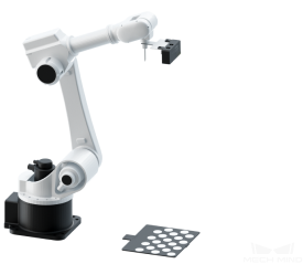
When the TCP touch method is used, the calibration board is placed on the object plane and a sharp-tipped tool with known dimensions is installed on the robot flange. Then, the robot will be moved to let the center point of the tool touch the cross center points of the calibration circles. As shown in the following figure, the values of A and B are known, and the value of X can be obtained. When the calibration board is not fixed on the flange, the value of A can be calculated by touching the cross center points of the calibration circles on the calibration board using a sharp-tipped tool with known TCP coordinates.
Equations for calculating the transformation relationship between the camera and robot reference frames are shown in the following figure.
Calibration in the EIH Scenario (TCP Touch)
When the TCP touch method is used, the calibration board is placed on the object plane and a sharp-tipped tool with known dimensions is installed on the robot flange. Then, the robot will be moved to let the center point of the tool touch the cross center points of the calibration circles. As shown in the following figure, since the values of A, B and C are known, the value of X can also be obtained.
Equations for calculating the transformation relationship between the camera and robot flange reference frames are shown in the following figure.
Eye to Eye Calibration
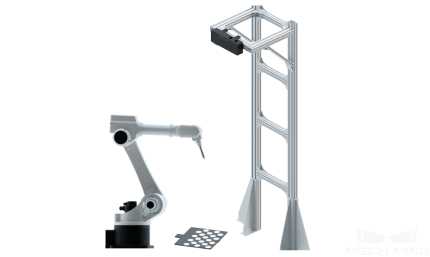
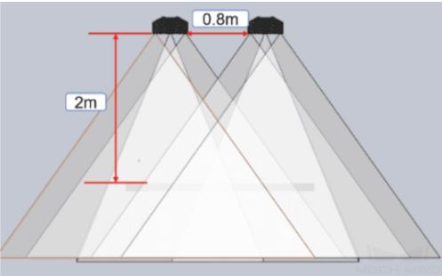
Using double cameras can expand the camera field of view and improve the point cloud quality of the two cameras’ overlapping part, as shown in the following figure.
In the Eye to Eye calibration scenario, two cameras, one as main camera and the other as sub-camera, are mounted on a stand independent of the robot. Eye to Eye calibration will not only calibrate the extrinsic parameters for the two cameras, but also calibrate the pose relationship between the two cameras. For the Eye to Eye calibration scenario, Mech-Vision provides a standard Eye to Eye calibration procedure.
Tip
The two cameras used should have the same resolution and the overlapping area of their field of view (2D&3D) should cover the entire working area.
Eye to Eye calibration supports only the multiple random calibration board poses method for calibration data collection, and supports both automatic and manual calibration modes.
