Data Acquisition and Data Types
In the Camera Viewer interface, you can perform image capturing and view the obtained 2D image, depth map, or point cloud.
Buttons for performing image capturing.
Switch the displayed data type.
Image Capturing
After the camera is successfully connected, you can start capturing images by clicking on the buttons.
The two buttons in the interface correspond to two modes of scanning.
Button |
Mode |
Description |
Continuous Scan |
Capture images at regular time intervals. The last obtained 2D image, depth map and point cloud are displayed. |
|
Scan Once |
Capture image once. |
Data Types
After the camera starts capturing images, you can view the obtained object information in the following data types. You can switch between the data types by clicking on the corresponding tabs at the top of the Image Display area.
Data type |
Description |
2D Image |
2D black-and-white/color image (depending on whether the camera is a color camera) |
Depth Map |
2D image containing depth information. The value of each pixel is the calculated distance from the camera to points on the object surfaces. |
Point Cloud |
The collection of points in the 3D space that reflect object surface features |
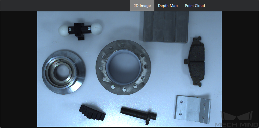
2D Image
Below is an example of a 2D image. Scroll to zoom in/out. Right-click on the image and select Reset View to reset the zoom.
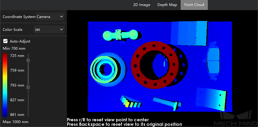
Depth Map
Below is an example of a depth map. Scroll to zoom in/out. Right-click on the image and select Reset View to reset the zoom.
The left panel provides the following options:
Coordinate System: where you can select the reference frame for displaying the depth information.
Camera: the depth information is displayed in the camera reference frame.
Customized: the depth information is displayed in the user reference frame. For detailed information on setting a user reference frame, please refer to Set User Coord System.
Color Scale: select to display the depth information in Jet color scale or grayscale.
Auto-Adjust: if checked, the two end colors are used to represent the smallest and largest depth values. If unchecked, you can adjust the correspondence between color and depth values. The min and max depth values are the depth lower and upper limit values set in the Depth Range parameter.
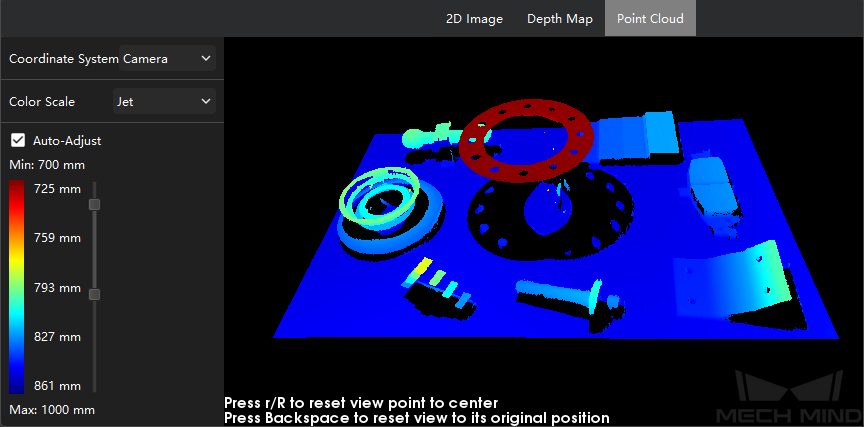
Point Cloud
Below is an example of a point cloud.
The following actions can be used to adjust the view of the point cloud:
Scroll: zoom in/out.
Hold the left mouse button and drag: rotate the point cloud.
Hold down the scrolling wheel and drag: move your point of view.
Press R key: reset the point of view to center.
Press Backspace key: reset the view of the point cloud to default.
The left panel provides the following options:
Coordinate System: where you can select the reference frame for displaying the depth information.
Camera: the depth information is displayed in the camera reference frame.
Customized: the depth information is displayed in the user reference frame. For detailed information on setting a user reference frame, please refer to Set User Coord System.
Color Scale: select to display the depth information in Jet color scale or grayscale.
Right-clicking on the Image Display area provides the following options:
Save Point Cloud: save the point cloud in PLY format (unit: mm).
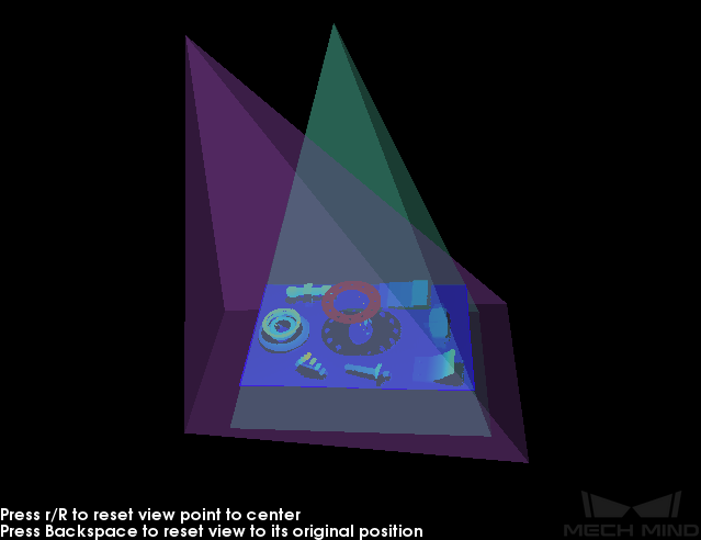
Show Frustrum: display the view frustums (fields of view) of the projector and the camera lens.
Show Axes: show the axes of the camera reference frame.


