Camera Diagram
Camera Front
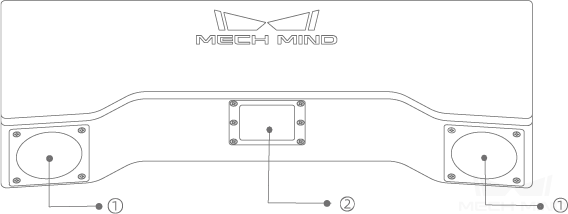
No. |
Name |
Function |
① |
Camera lens |
Capture images |
② |
Emitter |
Emit structural light |
Camera Back
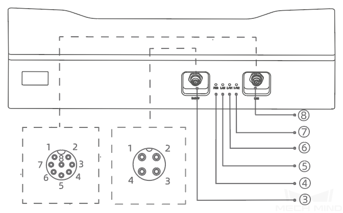
No. |
Name |
Function |
③ |
DC 24V port |
1: GND 2: GND 3: 24 V DC 4: 24 V DC |
④ |
PWR indicator light |
The indicator light turns on when power is supplied to the camera, and off otherwise. |
⑤ |
LAN indicator light |
The indicator light turns on when the camera is connected to the Ethernet, and off otherwise. * Gigabit network: green * Megabit network: yellow |
⑥ |
I/01 |
N/A |
⑦ |
I/02 |
N/A |
⑧ |
LAN port |
1: MD3_P 2: MD2_N 3: MD2_P 4: MD0_P 5: MD1_P 6: MD0_N 7: MD3_N 8: MD1_N |
Hint
The above diagrams are for illustration only; the actual product may differ.