Interface
This section introduces the interface of the Mech-Eye Viewer and includes the instructions on using the Device Finder and the Camera Viewer.
Device Finder
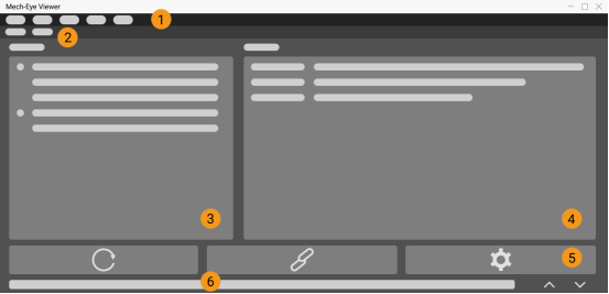
After opening Mech-Eye Viewer, the software shows the device finder interface, as in the figure below.
This interface is for connecting the camera to Mech-Eye Viewer. In this interface, you can view the list of connectable cameras and their information, connect a camera, and set the camera IP.

Device Finder’s Interface
Device Finder’s Interface
No. |
Component |
Use |
1 |
Menubar |
Switch software languages, switch users, view version information, and start virtual cameras. |
2 |
Switching tabs |
Switch between device finder and camera viewer. |
3 |
Detected cameras list |
View all available cameras and their model info in the current network. |
4 |
Camera info |
View the model, IP address, port, serial number, firmware version of the selected camera. |
5 |
Toolbar |
Refresh camera list, connect camera and set camera IP. |
6 |
Log |
View the status of the client program over time by scrolling up and down. |
Device Finder’s Toolbar
Feature |
Note |
Refresh camera list |
If the camera is powered on and connected to the current network, but does not appear in the camera list, please refresh the camera list. After refreshing, the camera will appear in the list of detected cameras. |
Connect a camera |
Select a camera, and click to connect the camera. |
Set camera IP |
For checking the machine’s network connection and setting the camera’s IP address. |
Camera Viewer
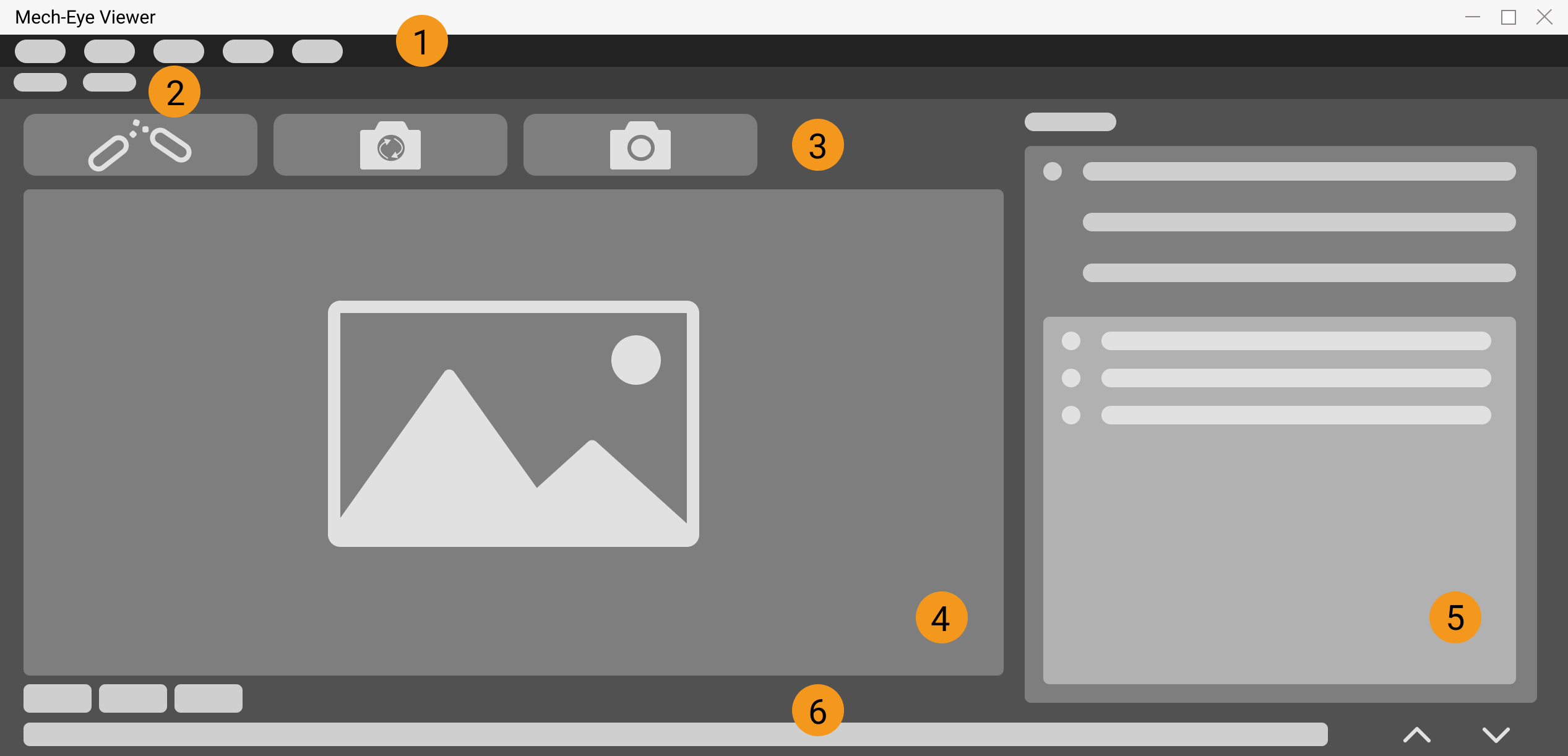
After the camera is successfully connected, the software will display the camera viewer interface, as shown in the figure below.
In this interface, you can capture images, switch the displayed data type, and adjust image and data information by adjusting parameters.

Camera Viewer’s Interface
The components and their uses are listed below.
No. |
Component |
Use |
1 |
Save image, switch software language, switch user, view version information, start virtual camera, open image analysis tools. |
|
2 |
Switching tabs |
Switch between device finder and camera viewer. |
3 |
Capture images or disconnect the camera. |
|
4 |
View images captured by the camera, and switch between displayed data types: 2D image, depth map, point cloud. |
|
5 |
View and adjust image parameters, and save parameter groups for different purposes. |
|
6 |
Log |
View the status of the client program over time by scrolling up and down. |
Camera Viewer’s Toolbar
Icon |
Name |
Use |

|
Disconnect |
Disconnect the currently connected camera. |

|
Continuous Scan |
Let the camera continuously capture images and view the images, depth maps, and point clouds. |

|
Scan Once |
Let the camera takes a single image and view the image, depth map, and point cloud. |
Camera Viewer’s Image Display
Through View in the menubar, you can select the type of data to be displayed, and you can switch the display data type in the lower-left corner.
Option |
Description |
2D image |
View 2D images captured by the camera. |
Depth map |
View depth maps captured by the camera. |
Point cloud |
View point clouds captured by the camera. |
Parameters
Visibility
Visibility options include Beginner and Expert. More parameters are available for adjustment in Expert mode. It is recommended to choose the Beginner mode first; if the quality of the 2D image, depth map, or point cloud is not satisfactory, please choose the Expert mode.
Config group
By default, parameters of the software are all expanded and all parameters that can be adjusted are displayed.
Icon |
Use |
|
Options: default, calib (calibration). |
Click the small triangle on the right side of the icon to view all parameter groups, please select a parameter group based on your needs. |
|
|
Expand all parameters. |
|
Collapse all parameters. |
|
Add a new parameter group. |
|
Delete the current parameter group. |
|
Rename the parameter group. |
|
Save the parameter set. Shortcut: Ctrl S. |
|
Reset the parameter group (restore the factory settings). |
|
Import parameter groups. |
|
Export parameter groups. |
Note
default is a default parameter group and cannot be deleted.
It is recommended to create corresponding parameter groups for different projects.
Property (Parameter) Panel
The panel consists of two parts: parameter name and value. It is mainly used to view parameter definitions, set regions of interest, and adjust parameters for 2D images, depth maps and point clouds. For details, please see Parameter Adjustment.
Parameter name:
Click on the parameter name to view its definition. Double-click on a parameter category (2D parameters, 3D parameters, point cloud processing, etc.) to expand/collapse all parameters under a category.
Value:
For setting the region of interest or adjusting the camera settings for obtaining the optimal 2D images, depth maps, or point clouds.